Great Wall engine 4G64S4M. Manual — part 10
11-34
ENGINE
CYLINDER HEAD AND VALVE
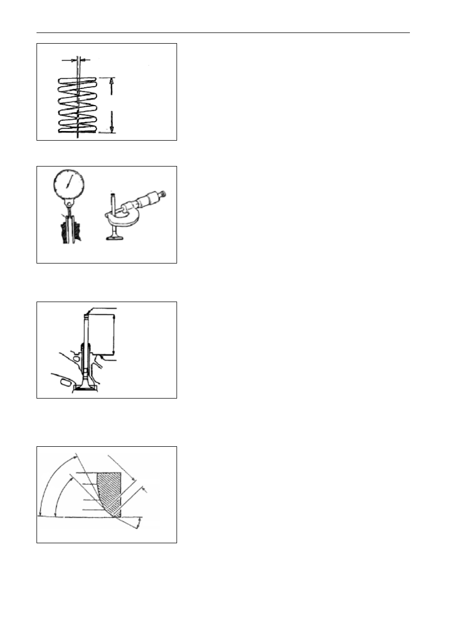
Valve Spring
(1)
Measure the free spring height, in case it is less than the limit
value, change the spring.
Standard value: 51.0 mm
Limit value: 50.0 mm
(2)
Measure the perpendicularity of the center line with the surface
of the spring, if the gradient exceeds the limit, change the spring.
Standard value:
2
Limit value: 4
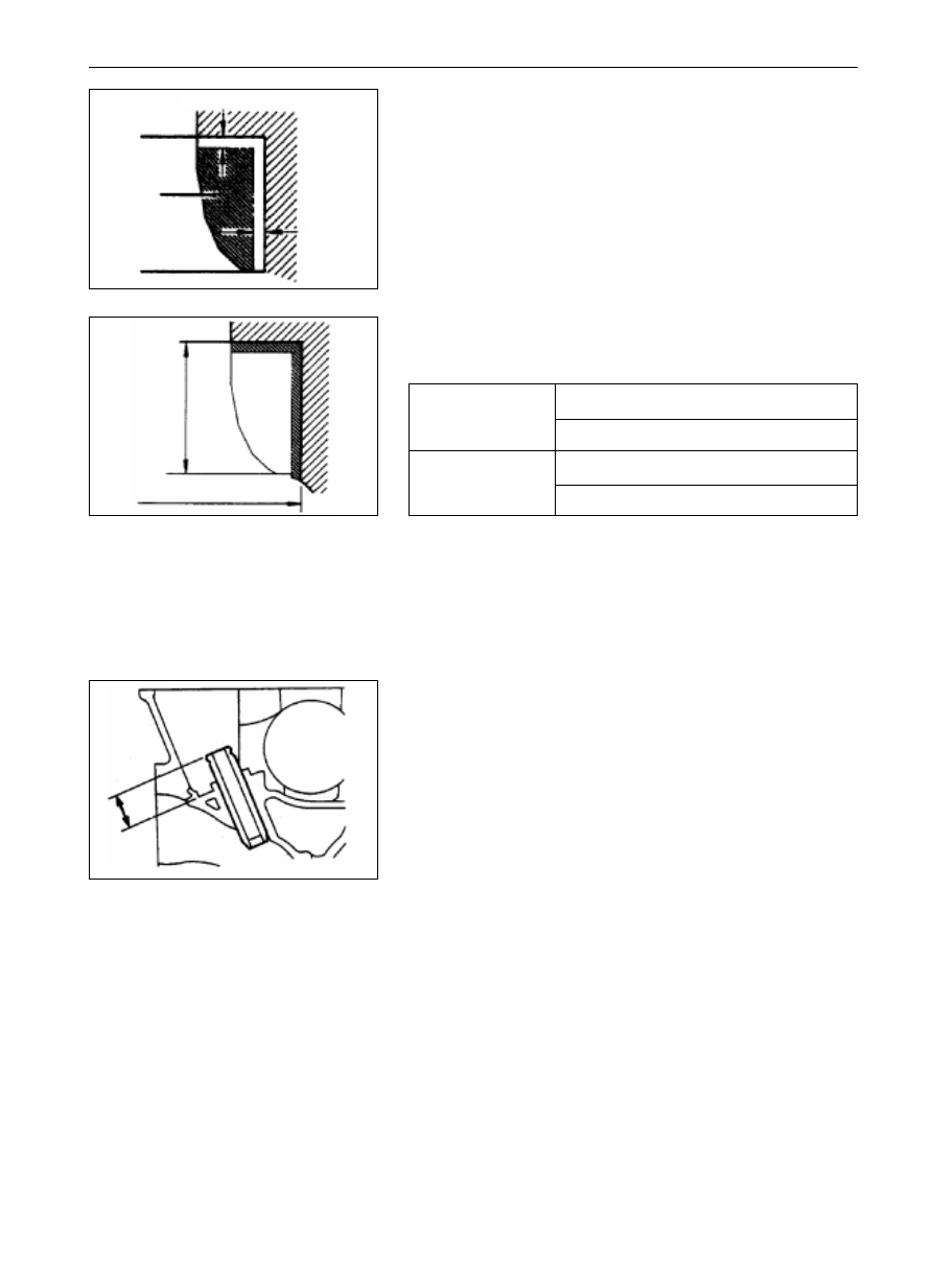
Valve Guide
(1)
Measure the clearance between the valve guide and the valve
stern, if the clearance exceeds the limit value, Change the valve
guide or valve or both of them.
Standard value:
Intake value . . . . . . ... 0.02
0.05mm
Exhaust value . . . . . . 0.03
0.07mm
Limit value:
Intake value . . . . . . ... 0.10mm
Exhaust value . . . . . . 0.15mm
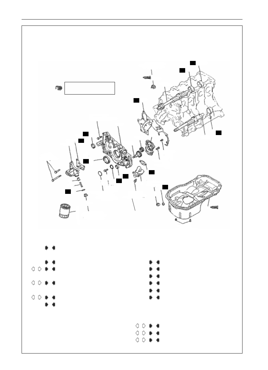
Valve Seat
1) Assemble the valve and measure the protruding height of the
valve stern between the end of valve stern and valve spring seat.
In case the measured value exceeds the specified limit, change
the valve seat.
Standard value:
Intake value . . . . . . ... 49.30mm
Exhaust valve . . . . . . 49.30mm
Limit value:
Intake value . . . . . . ... 49.80mm
Exhaust value . . . . . . 49.80m
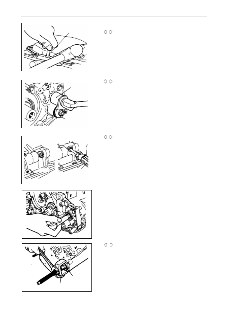
Main Points on Trimming of Valve Seat
(1)
Before trimming the valve seat, check the clearance between the
valve guide and the valve rod, conduct the trimming where
necessary.
(2)
Trim the width and angle of the valve seat to the specified value
with the Muller.
(3)
Grind the valve seat with the corresponding valve with grinding
paste after trimming the valve seat. Then check the protruding
height of the valve stern (refer to inspection items of valve seat).
angle belwee cerrter line of spring and plun bine
of subface
free spring height
1EN0264
valve
guide
inside diamter of
valve guide
outside diameter
of valve guide
1EN0279
endof valve stern
protruding height
of valve stern
seat face of valve
spring
DEN0212
0.9
1.3mm
43.5
44
6EN0491
11-35
ENGINE
CYLINDER HEAD AND VALVE
Main Points in Change of Valve Seat
(1)
Cut out part of the valve seat to be changed so as to thin and
remove it.
(2)
Trim the valve seat holes on the cylinder head as per the outside
diameter of the enlarged valve seat.
Diameter of valve seat ring:
Enlarged dimension: 0.30
34.435-34.455
Enlarged dimension: 0.60
34.735-34.755
Enlarged dimension: 0.30
31.935-31.955
Enlarged dimension: 0.60
32.235-32.255
Diameter of valve guide hole on cylinder head:
Dimension plus 0.05:
11.05-11.068
Dimension plus 0.25:
1.25-11.268
Dimension plus 0.50:
1.50-11.518
(3)
Press the valve guide as shown in the figure until its protrusion
meets the specification.
Standard value: 14mm
0.3
Notice:
Press down the valve guide from the superface of the cylinder
head.
The length of the inlet valve guide is different from that of the
exhaust valve guide. (inlet valve: 45.5, exhaust valve: 50.5
(4)
Inset the new valve after mounting the valve guide and inspect
whether it can move smoothly.
0.5
1mm
1EN0274
0.5
1mm
cut out
height of valve
seat ring
enlarged lnside diameter
1EN0275
protrusion
1EN0106
(3)
Before assembling the valve seat ring, heat the cylinder head to
250 or so, or cool the valve seat ring in the liquid nitrogen so as
to prevent it from being seizing in the cylinder head.
(4)
Trim the valve seat to the specified width and angle with the
milling cutter of valve seat (refer to the Main Points for Trimming
of Valve Seat)
Main Points for Change of Valve Guide
(1)
Press the valve guide out toward the cylinder block with the
presser.
(2)
Process the valve guide hole of the cylinder head to make it reach
the dimension of the enlarged valve guide to be mounted.
Notice:
Do not apply the new valve guide with same dimension with the
dismantled one.
Inlet valve seat
Exhaust valve seat
11-36
ENGINE
CYLINDER HEAD AND VALVE
10N.m
1.0Kgft
27
29
24
26
23
18
19
17
24N.m
2.4Kgifm
22
16
15
14
13
12
11
44N.m
4.5Kgfm
7
8
2
3
6
25
23N.m
2.4Kgfm
36N.m
3.7Kgfm
5
9
39N.m
4.0Kgfm
7N.m
0.7Kgfm
4
19N.m
1.9Kgfm
20
16N.m
1.7Kgfm
10N.m
1.0Kgfm
28
10
N
N
N
N
N
N
21
N
N
N
N
N
N
All inside parts should be
coated with the engine oil
19N.m
1.9Kgifm
Disassembly Process
1. lubricating oil filter
2. drain plug
3. drain plug washer
4. oil sump
5. oil collector and filter
6. washer of oil collector and filter
7. plug
8. o-ring
9. flange bolt
10. oil pressure switch
11. relieve pug
12. gasket
13. pressure relief spring
14. pressure relief plunger
15. oil filter bracket
16. washer of oil filter bracket
17. lubricating pump cover
18. driven gear of lubricating pump
19. driving gear of lubricating pump
20. front oil seal of crankshaft
21. oil seal of lubricating pump
22. oil seal of balancing shaft
23. front cover
24. front cover washer
25. left balancing shaft
26. right balancing shaft
27. front bearing of right balancing shaft
28. left balancing shaft bearing
29. rear bearing of right balancing shaft
N
M
L
A
K
B
I
G
H
H
F
D
E
J
C
C
D
B
E
A
E
FRONT COVER, OIL PUMP, BALANCE SHAFT ,OIL PAN
DISMANTLE AND ASSEMBLY
11-37
Main Points of Disassembly
Disassembly of Oil Sump
(1)
Disassemble all of the bolts of oil sump.
(2)
Tap the SST into the clearance between the cylinder block and
the oil sump.
Notice:
Do not replace the SST with screwdriver or chisel, otherwise the oil
sump will deform and leak oil.
Disassembly of Plug
(1)
In case the plug is over tight, tap it lightly with hand hammer
for two or three times, and it will become loose.
Disassembly of Flange Bolt
(1)
Tear down the plug from the side of cylinder block.
(2)
Insert the screwdriver (with pole diameter of 8mm) in the plug
hole to fasten the balancing shaft.
A
B
C
MD998727
6EN0698
MD998162
6EN0909
6EN1026
screwdrive
plug
ENGINE
CYLINDER HEAD AND VALVE
6EN0565
3EN0207
front bearing
MD998372
D
(3)
Loosen the flange bolts
Disassembly of Front bearing of Right Balancing
shaft
(1)
Dismantle the front bearing of the right balancing shaft from
the cylinder block with the SST.
Remark: The front bearing must be dismantled first, otherwise, the
puller for rear bearing cannot be applied.
Нет комментариевНе стесняйтесь поделиться с нами вашим ценным мнением.
Текст