Great Wall engine 4G64S4M. Manual — part 9
11-30
ENGINE
CYLINDER HEAD AND VALVE
CYLINDER HEAD AND VALVE
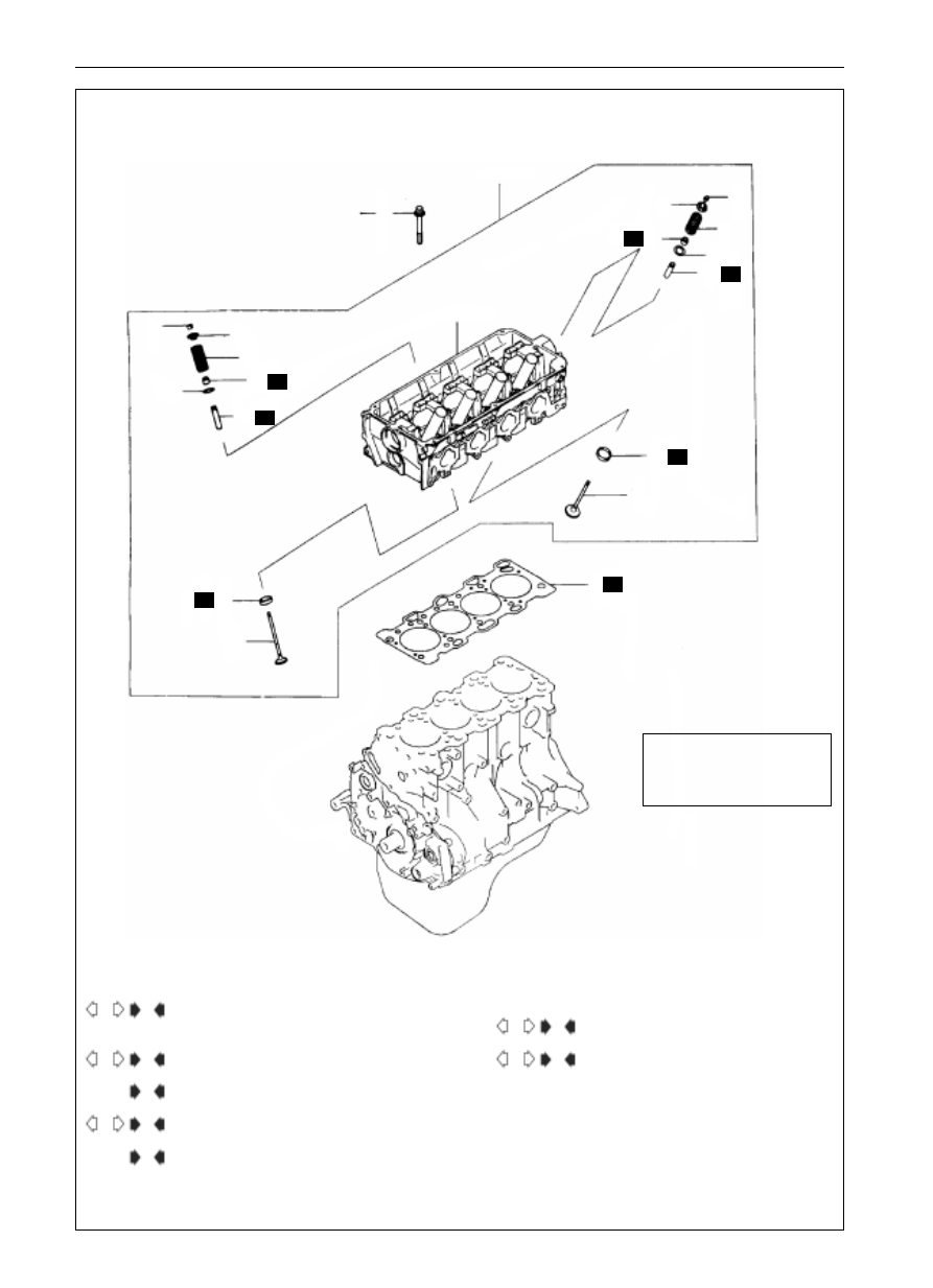
DISASSEMBLY AND ASSEMBLY
78N.m
thorough
looseness
20N.m 90
+90
1
2
8
9
10
14
17
15
20
5
4
6
13
16
18
7
19
11
3
12
All parts inside should be
coated with enging oil in
assembly
6EN1386
N
N
N
N
N
N
N
B
1.
cylinder head bolts
2.
cylinder head cluster
3.
head gasket
4.
valve lock clamp
5.
upper site of valve spring
6.
valve spring
7.
inlet valve
8.
valve lock clamp
9.
upper site of valve spring
10. valve spring
11. exhaust valve
11. valve oil seal
12. valve spring seat
13. valve spring
14. valve spring seat
15. inlet valve guide
16. exhaust valve guide
17. inlet valve seat
18. exhaust valve seat
19. cylinder head
B
C
B
B
C
C
A
C
A
A
D
Disassembly Procedure
11-31
ENGINE
CYLINDER HEAD AND VALVE
MB991654
MD998772
9EN0062
9EN0063
MD998774
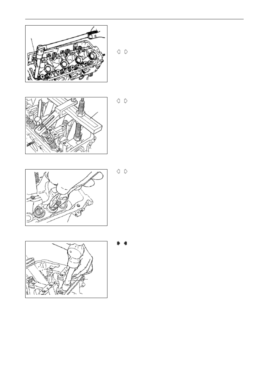
Notices after Disassembly
The disassembled parts should be sorted as per the cylinder number
and the intake/exhaust parts.
Dismantle of Cylinder head Bolts
(1)
Loosen the bolts of each cylinder heads with SST. The looseness
should be even and gradual.
Dism Dismantle of Valve Lock Clamp
(1)
The dismantled parts such as the valve and spring should be
marked with the cylinder number and signboard of mounting
position and kept well so as to prepare the later reuse in assembly.
Dismantle of Valve Oil Seal
(1)
The valve oil seal must not be reused.
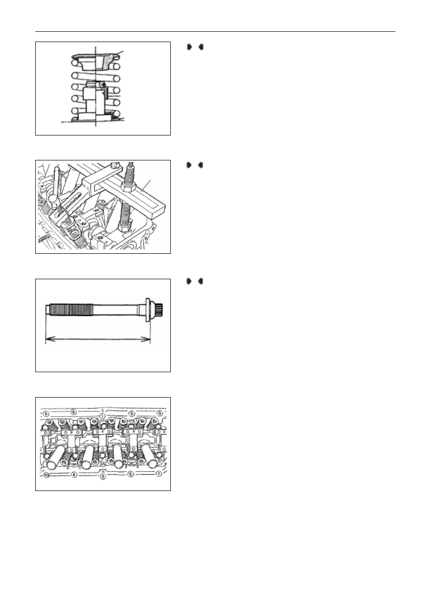
Mount of Valve Oil Seal
(1)
Mount the lower site of valve spring.
(2)
Mount the valve oil on the valve guide with SST tools. Incorrect
mount will lead to leakage.
Notice:
The valve oil seal must not be reused.
A
A
C
B
11-32
ENGINE
CYLINDER HEAD AND VALVE
Mount of Valve Lock Clamp
(1)
In case the valve spring is over compressed, it will contact the
bottom of the valve spring and thus damage the valve oil seal.
Mount of Cylinder head Bolts
(1)
When assembling the bolts of cylinder head, the bolt length
should be identified to meet the limit value, otherwise, change the
bolts.
Limit Value (A): 99.4 mm (Max)
(2)
Coat the engine oil on the threaded part of the bolts and on the
gasket.
(3)
Tighten the bolts in the tightening order to the specified torque
with SST (MB991654).
Tightening Moment: 78N.m
(4)
Loosen all parts thoroughly.
(5)
Tighten the bolts with the torque of 20N.m in the tightening
order.
upper site of
spring
valve oil seal
lower site of
spring
identifi cation
6EN0437
MD998772
9EN0062
bolt length
6EN0782
6EN0695
C
D
Mount of Valve Spring
(1)
The valve spring shall be mounted in such way that the spring end
with identification color faces the upper site of the valve spring.
B
11-33
ENGINE
CYLINDER HEAD AND VALVE
paint marks
6AE0297
90
90
9EN0064
contatc position
(the center of slope)
edge thickness
6EN0542
(6)
Mark a straight line with paint on the heads of cylinder head bolts
and the cylinder head.
(7)
Tighten the cylinder head bolts by 90
in tightening order.
(8)
Tighten the bolts by another 90
, ensuring the paint marks on
the heads of cylinder head bolts and the cylinder head should be
in alignment.
Notice:
If the screwing angle of the bolt is less than 90, correct
tightening moment cannot be expected. Therefore, sufficient
importance should be attached to whether the screwing
angle is correct when tightening the bolts.
In case the bolts are over tightened, they should be
loosened thoroughly and then re-tighten them from Step (1).
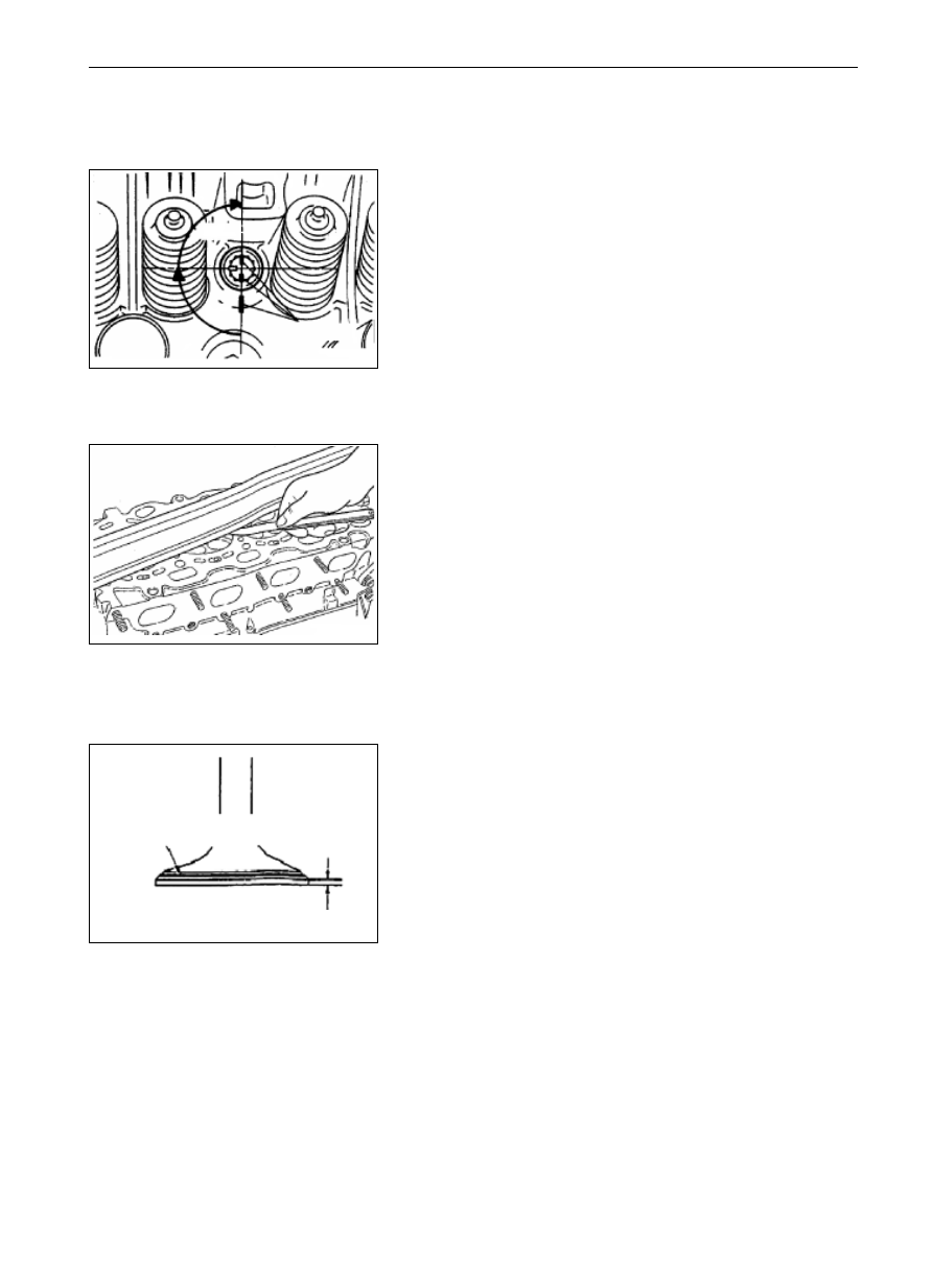
Inspection on Cylinder head
(1)
Inspect the Planeness of the surface of cylinder head with ruler
and feeler.
Standard value: 0.03mm
Limit value: 0.2mm
(2)
The deformation should be corrected by grinding in case it
exceeds the limit value.
Grinding limit value: * 0.2mm
Total grinding amount of the cylinder head with the
cylinder block together.
Height of cylinder head (standard value for the new): 119.9
120.1mm
Valve
(1)
Check whether work faces of valve contact correctly. If not,
polish the valve applied and regrinding it. The contact face of
valve seat should be in consistency with the center of work face
of the valve.
(2)
In case the edge thickness exceeds the limit value, change the valve.
Standard edge thickness value:
Intake value . . . . . . ... 1.0 mm
Exhaust value . . . . . . 1.2 mm
Application limit value:
Intake value . . . . . . ... 0.5 mm
Exhaust value . . . . . . 0.7 mm
(3)
Measure the total valve height, in case it is less than the limit
value, change the valve.
Standard value:
Intake value . . . . . . ... 112.30mm
Exhaust Value . . . . . . 114.11mm
Limit Value:
Intake value . . . . . . ... 111.80mm
Exhaust Value . . . . . . 113.61mm
Нет комментариевНе стесняйтесь поделиться с нами вашим ценным мнением.
Текст