Great Wall engine 4G64S4M. Manual — part 14
11-50
ENGINE
CYLINDER HEAD AND VALVE
CRANKSHAFT, CYLINDER BLOCK AND
FLYWHEEL
DISASSEMBLY AND ASSEMBLY
13
5
6
3
2
11N.m
132N.m
8.8N.m
4
11N.m
11
10
9
8
7
25N.m+90
~100
12
Smear the engine oil on
all moving parts
N
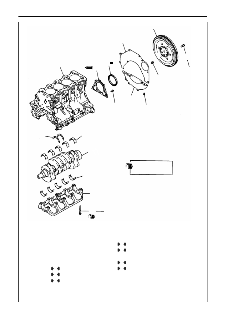
Disassembly Procedure
1. flywheel bolt
2. flywheel
3. rear cover plate
4. bell jar
5. rear oil seal cap
6. oil seal
7. main bearing cap bolt
8. main bearing cap
9. low bearing of crankshaft
10. crankshaft
11. bearing on crankshaft
12. thrust bearing of crankshaft
13. cylinder block
E
D
C
C
B
B
A
11-51
ENGINE
CYLINDER HEAD AND VALVE
Inspection
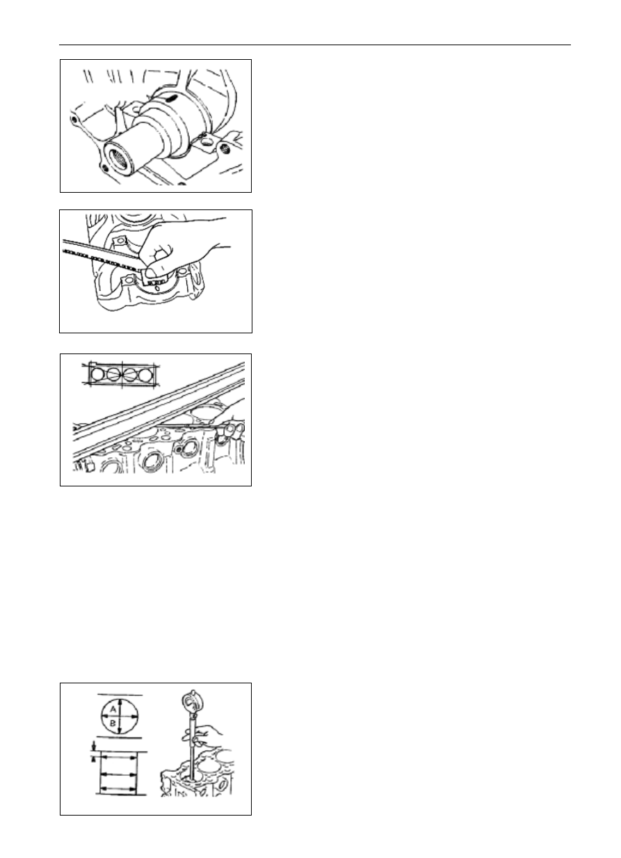
Measurement for Crankshaft Play (clearance gauge of plastic
cord)
(1)
Clean the oil on the main journal and the inner race of bearing.
(2)
Mount the crankshaft.
(3)
Cut the clearance gauge of plastic cord in the length that is the
same with the width of bearing, then put them on the crankshaft
journal and ensure them are parallel with the axial center line.
(4)
Mount the main bearing cap carefully and tighten the bolts as
per the specified torque.
(5)
Tear down the main bearing cap.
(6)
Measure the Max width of the flattened plastic cord with the
gauging ruler printed on the package bag of the clearance
gauge of plastic cord, thus acquiring the clearance value.
Standard value: 0.02
0.04mm
Limit value: 0.1mm
Cylinder Block
(1)
Conduct a visual observation for deflects such as scoring, rust
and corrosion, etc. or conduct an inspection with the fluid
testing agent. In case the cylinder block has obvious deflect,
repair or change it.
(2)
Check the plane on cylinder block for warp with ruler and
feeler, and be sure there should be no washer scraps or other
alien materials on the surface.
Standard value: 0.05mm
Limit value: 0.1mm
(3)
In case the cylinder block has over large warp, change or
correct it within the permitted range.
Grinding limit: 0.2 mm
The max sum of thicknesses of the cylinder block and
cylinder head that is permitted to cut out is 0.2 mm.
Height of cylinder block (new): 290mm
(4)
Check whether the cylinder wall has scoring or the cylinder is
seized, in case the requirement is not met, correct (enlarge the
dimension) or change them.
(5)
Measure the inner cylinder and cylindricity of the cylinder
with the cylinder gauge, the cylinder should be corrected by
enlarging the diameter on condition the abrasion is serious,
and change the piston and piston ring. Measurement positions
are shown in the figure below.
Standard value:
Inside diameter of cylinder: 86.50
86.53MM
Cylindricity:
0.01mm
clearance gauge of
plastic cord
6EN0703
6EN0623
9EN0074
12mm
center
bottom
6EN0553
11-52
ENGINE
CYLINDER HEAD AND VALVE
thrusting
direction
piston diameter
6EN0554
6EN1557
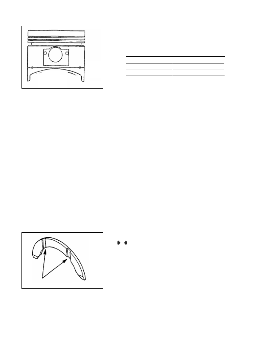
Re-boring of Cylinder Diameter
(1)
The diameter for the enlarged piston should be determined
according to the max cylinder diameter.
Identification of piston diameter
Remark: Dimension mark is printed on the top of piston.
(2)
Measure the diameter of the cylinder to be used, the measure-
ment should be conducted in the thrusting direction shown in
the figure below.
(3)
Calculate the reparation dimension of the cylinder diameter
according to the outside diameter of the piston.
Reparation dimension = outside diameter of piston +
(clearance between piston and cylinder)
0.02 mm
(hone grinding)
(4)
Repair each cylinder to the dimension of reparation.
Notice:
When honing the cylinder, in order to prevent the error
caused by the increased temperature, conduct the reparation
as the order below: No.2
No.4 No.1 No.3
(5)
Hone the cylinder to its final diameter (piston diameter +
clearance between the piston and cylinder).
(6)
Check the clearance between the piston and the cylinder.
Standard value: 0.02
0.04mm
Remark:
When repairing the cylinder, the four cylinders should be in the
same dimension, do not only enlarge one cylinder.
Main Points of Mount
Mount of Thrusting Bearing of Crankshaft
(1)
Mount the thrusting bearing of crankshaft (2 sheets) on the 3rd
main shaft hole of cylinder block. Coat a little engine oil on the
surface of thrusting bearing to facilitate the mount.
(2)
The thrusting bearing side with groove should face to the
handle arm of the crankshaft.
dimension
Identification mark
Plus 0.50
0.50
Plus 1.00
1.00
A
11-53
ENGINE
CYLINDER HEAD AND VALVE
No.3
No.2
No.1
No.4
No.5
6EN0705
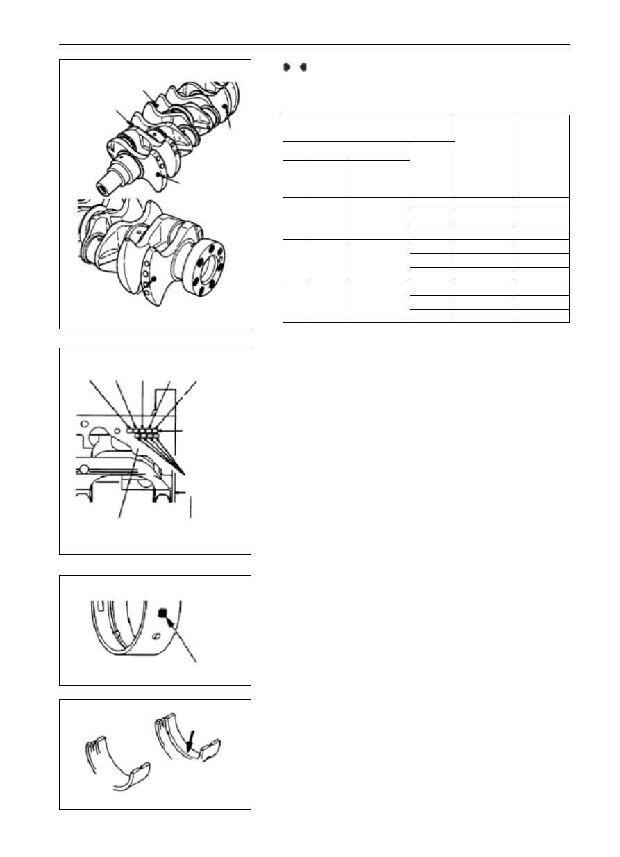
identification mark for dimension of main bearing
No.1
No.2
No.3 No.4
No.5
identification
mark of main
bearing hole
dimension mark
of cylinder in-
side diameter
sub-face of cylinder
block
rear end face of cylinder
block
6EN1632
identification mark or color for crankshaft bearing
identification mark or color
6EN1096
groove
upper
lower
6EN1558
Mount of crankshaft bearing
(1)
Select the bearing that meets the dimension of crankshaft main
journal as per the form below.
B
Bearing Selection, for instance:
In case the identification color of the crankshaft main journal is
yellow, and the identification mark for main shaft aperture is
1, select the Bearings of No. 1,2, 4 and 5 with identification
mark
2 and identification color yellow or the No. 3
bearing with identification mark
1 and identification color
green.
In case there is no identification paint on the crankshaft, measure
the main journal and select the corresponding bearing as per the
measured value.
(2)
Mount the bearing with groove at the side of cylinder block.
(3)
Mount the bearing without groove at the side of main bearing
cap
0
1 Green
0 Black
Yellow 56.994
57.000
1
2 Yellow
1 Green
2
3 None
2 Yellow
0
2 Yellow
1 Green
None
56.988
56.994
1
3 None
2 Yellow
2
4 Blue
3 None
0
3 None
2 Yellow
White
56.982
56.988
1
4 Blue
3 None
2
5 Red
4 Blue
Combination of crankshaft main journal and
main shaft aperture
I d e n t i f i c a t i o n
marks and colors
for bearings of
Journal 1,2 and 5
Identification
marks and
colors for
bearings of
No 3 journal
Crankshaft main journal
Identification
mark of main
shaft aperture
Groups
Identifica-
tion color
Diameter
(mm)
Нет комментариевНе стесняйтесь поделиться с нами вашим ценным мнением.
Текст