Great Wall Hover. Manual — part 44
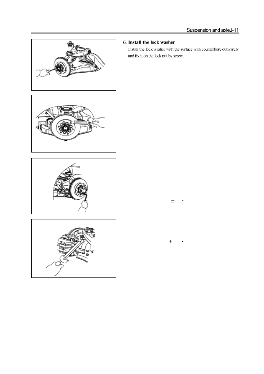
Remarks: If the screw installation hole on the lock washer can not
align with the screw hole on the lock nut, then it can remove the lock
washer and adjust he lock nut slightly (rotate in the direction of
Min. adjusting range ); then install the lock washer.
7. Recheck the pre-applied load
Use the spring tension meter to recheck the pre-applied load.
Pre-applied load (for starting): 28-56N
If the pre-applied load does not meet the specified value, it must remove
the lock washer and adjust it by the adjusting nut.
8. Install the hub cap
a. Coat the silicon rubber surface sealant on the matching surface of
hub and hub cap.
b. Coat the screw of the inner hexagon bolt with the screw lock sealant.
c. Use the inner hexagon bolt to fix the hub cap and ring flange on the
hub; tighten the bolt to the specified torque.
Tightening force: 45
5N
m
9. Install the disc brake
Install the disc brake on the steering knuckle and tighten the bolt to the
specified torque.
Tightening force: 140
10N
m
Steering knuckle
Disassembly of steering knuckle
1. Remove the disc brake and front hub
(Refer to section “Front Hub”)
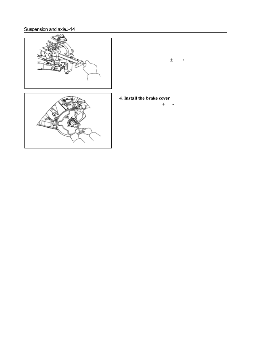
2. Remove the brake cover
special tools
special tools
special tools
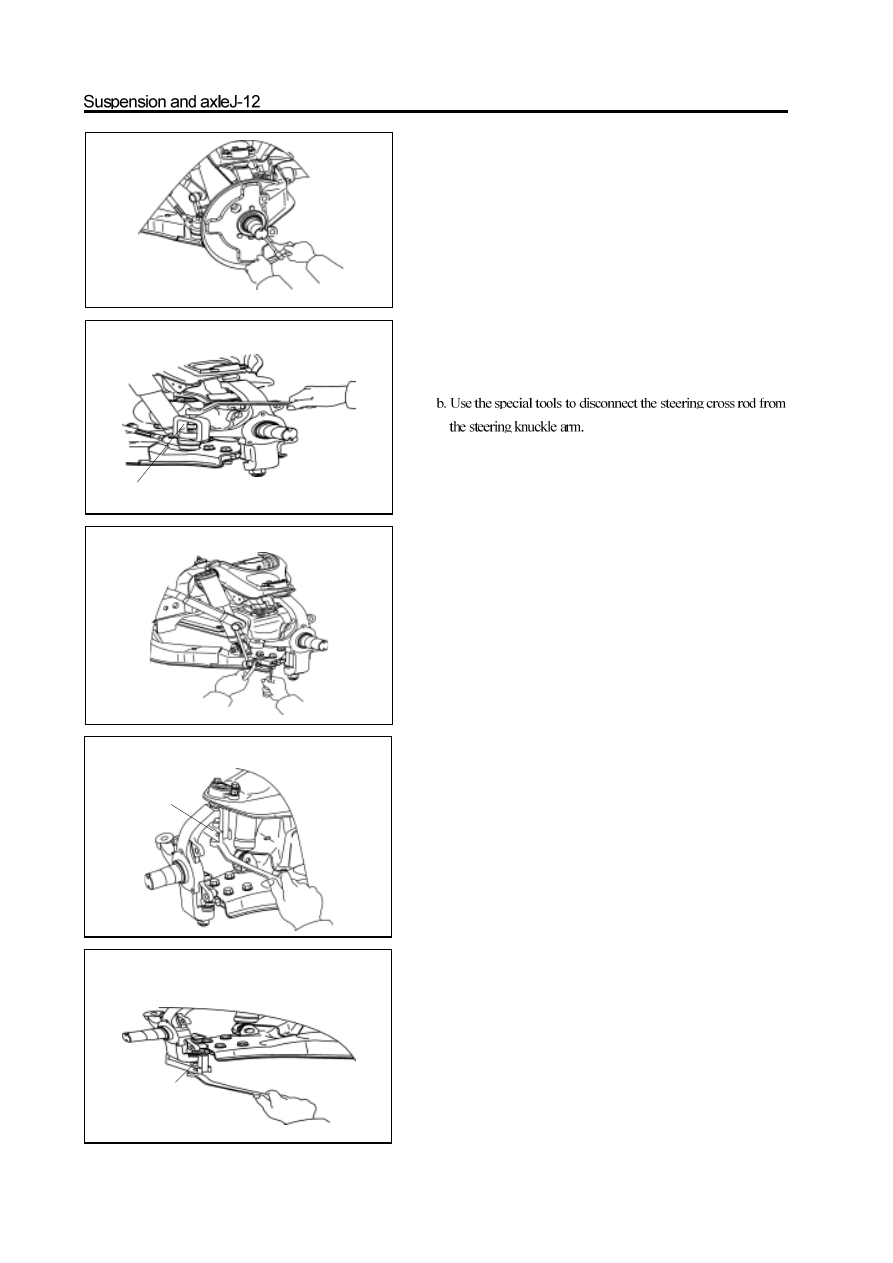
3. Disconnect the steering cross rod from the steering
knuckle arm
a. Remove the split pin and nut on the ball pin.
4. Disconnect the connecting rod of stabilizer bar from
lower arm
Use the inner hexagon spanner to fix the ball pin; remove the self-
locking nut.
5. Remove the steering knuckle
a. Remove the split pin and nut on the upper ball pin
b. Use the special tools to disconnect the steering knuckle from the
upper ball pin.
c. Remove the split pin and nut on the lower ball pin.
d. Use the special tools to disconnect the steering knuckle from
the upper ball pin.
e. Remove the steering knuckle.
Check and replacement of steering knuckle
Use the dye penetrant to check the steering knuckle for
crack.It should replace the steering knuckle if has crack.
Installation of steering knuckle
1. Install the steering knuckle
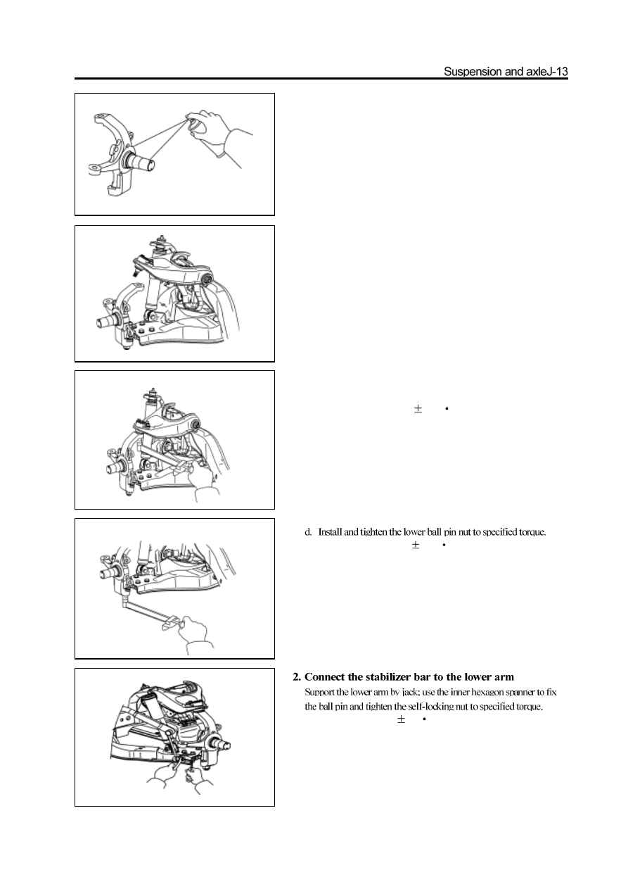
a. Install the lower ball pin on the steering knuckle and install the
slotted nut temporarily.
b. Press down the upper arm and connect the upper ball pin to the
steering knuckle. Install and tighten the nut to the specified torque.
Tightening force: 145
15N
m
c. Install the new split pin.
Remarks: It should align the notch of nut with the pinhole
when install the split pin; the nut can be tightened but not
loosed during the alignment.
Tightening force: 230
20N
m
e. Install the new split pin.
Remarks: It should align the notch of nut with the pinhole
when install the split pin; the nut can be tightened but not
loosed during the alignment.
Tightening force: 63
5N
m
3. Connect the steering cross rod to the steering
knuckle arm.
a. Tighten the slotted nut according to the specified torque.
Tightening force: 170
15N
m
b. Install the new split pin.
Remarks: It should align the notch of nut with the pinhole
when install the split pin; the nut can be tightened but not
loosed during the alignment.
Tightening force: 23
3N
m
5. Install the front hub and disc brake
(see section of front hub)
Нет комментариевНе стесняйтесь поделиться с нами вашим ценным мнением.
Текст