Great Wall Hover. Manual — part 3
Electrical system
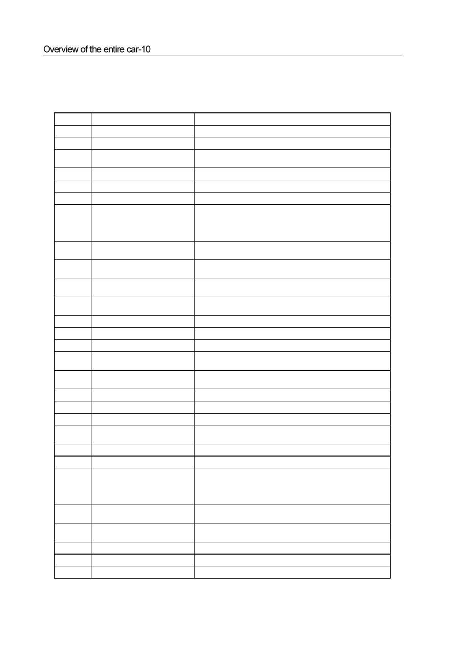
The structure and parameter of the electrical system are shown in table 7.
Table 7 Structure And Parameter of Electrical System
No.
Item
Structure and Parameter
1
Power, starting and charging system
1.1
Lines
Singe line system, voltage DC 12V, negative earth
1.2
Accumulator
55D26R maintenance free type, voltage 12V, 20 hours capacity 60Ah, storage
capacity 101min, low temperature starting current 475A
1.3
Starter
12V, 1.2kW
1.4
generator
Internally furnished with adjustor type generator. 14V, 90A
2
Illumination and signal system
2.1
Front illumination light
white, major high beam 60W,1 on the left and right respectively,
auxiliary high
beam
55W,1 on the left and right respectively, passing
lamp 55W,1 on the left and right respectively. Head light base center
height H: 920mm±20mm
2.2
Position light
Front position lamp:
white
, 5W,1 on the left and right respectively.
Rear parking lights: red, 5W,1 on the left and right respectively.
2.3 turn
light
Amber 。Front and rear turn light: 21W,1 on the left and right
respectively. Side turn light: 5W,1 on the left and right respectively,
2.4 Fog
light
Front fog light: white, 55W, 1 on the left and right respectively. Rear
fog light: red, LED,1 on the left and right respectively.
2.5 Brake
light
Red, 21W, 1 on the left and right respectively, high position brake light,
10W, 2 in the middle
2.6
License light
White, 5W, 1 on the left and right respectively.
2.7
Backup light
White, 21W, 1 on the left and right respectively.
2.8
Danger warning signal light
All the turning signal lights, danger alarm switch control
2.9
Back repeating reflector
Red, none triangle shape, forming combination light with the rear fog
light
2.10
Front, middle and back ceiling light
in the room
White. Front indoor ceiling light: 10W, 2 pieces. Middle indoor ceiling
light: 10W, 1 piece. Back indoor ceiling lights: 5W, 1 piece
2.11
Cigar lighter illumination
Blue, 3W, 1 piece
2.12
Ash tray illumination
White, 3W, 1 piece
3 Meter
system
3.1 Combined
instrument
Car speed odometer, engine speed indicator, water temperature meter,
fuel gage
3.2
Indicator lamp
Refer to the drawing
4 Auxiliary
electrical
system
4.1 Rain
wiper
system
Front and rear rain wiper DC motor. Front rain wiper: four rods type,
electric drive three gears (high and low speed + adjustable interval),
scraper 2 pieces, 55W. Rear rain wiper: single arm type, electric drive
one gear, with 1 scraper plate, 21W
4.2
Defogging, defrosting device
Front wind window hearing type, back wind window heating type
glass, switch control
4.3
Electric drive glass frame riser
Drive side general control, independent control oh other windows and
doors
4.4
Central control lock
With remote control
4.5
Camborne power socket
12V, 2 pieces
4.6
Radio, CD and loudspeaker
Stereo radio, six discs CD, four sound channels

Overview of the entire car-11
4.7 Cigar
lighter
12V,
1
piece
4.8
Horn
Treble and bass
4.9
Safety airbag
Electric main and auxiliary airbag
Checking and commissioning of the auxiliary components of car body:
1. Stop the car stably, check the doors, engine cover, fuel filling port cover, meter and tools box cover, front and rear ash
tray cover, floor center console sundries box cover, CD disc conveyer (VCD disc conveyer), power socket cover, etc. they
shall be reliable and flexible during starting, opening and closing, without blocking and insufficient closing and
abnormal sound;
2. The major lamp high beam and city beam, the alternating light, taillight, turn light, brake light, front and rear mist
light, malfunction alarm light, indoor light, instrument panel light, ignition switch light, etc. shall operate normally,
without the failure of no lighting,constant lighting and error lighting , etc;
3. Checking the performance of front head light
a. The high beam luminous intensity of each head light
20000 cd/ piece
b. Beam center left and right deviation (when the beam is irradiating on the screen of 10 m away):
Left light high beam: left 17 cm right 35 cm
Right light high beam: left 35 cm right 35 cm
Left light city beam: left 17 cm right 35 cm
Right light city beam: left 17 cm right 35 cm
c. Beam center height (when the beam is irradiating on the screen of 10 m away):
Head light city beam 0.7
0.9 H; head light high beam 0.9
1.0 H
H means the head light center height 920
20mm.
4. The adjustment of multi functional meter:
a. Drive the car onto the trench, insert the car speed transducer, drive the car to open places, press the ADJ switch for no less than
3 seconds, the orientation indicator begins to flash. Drive the car slowly for one circle within 2 minutes, the orientation
indicator will stop flashing, it shall points to the practical normal direction.
Note: E
east, W
west, S
south, N
north.
b. The adjustment of time:
Press the “MODE” switch for over 2 seconds, the time can be adjusted, press the MODE switch to adjust the minute, then
press the MODE again to adjust the hour, adjust the time through pressing the “
”and “
” key. After the time is adjusted,
press the ”MODE” switch for over 2 seconds to quit the time adjustment mode.
c. Check to see whether the absolute altitude meter and the car speed response display are working normally.
d. Drive the car onto the trench again, pull off the car speed transducer plug.
5. The adjustment of rain wiper nozzle cleaning mixture ejection height:
a. Put the ignition switch to the ”ON” position, open the rain wiper nozzle switch, the position of front cleaning mixture nozzle
shall be evenly distributed along the middle height of the front windshield glass from left to right.
b. The position of the rear cleaning mixture nozzle is deviated to right of the center of rear windshield glass for about 20mm-
120mm, and the height is within the scope of 50mm at the center of the glass. If the deviation is large, the nozzle needs to be
adjusted.
Air-conditioning system
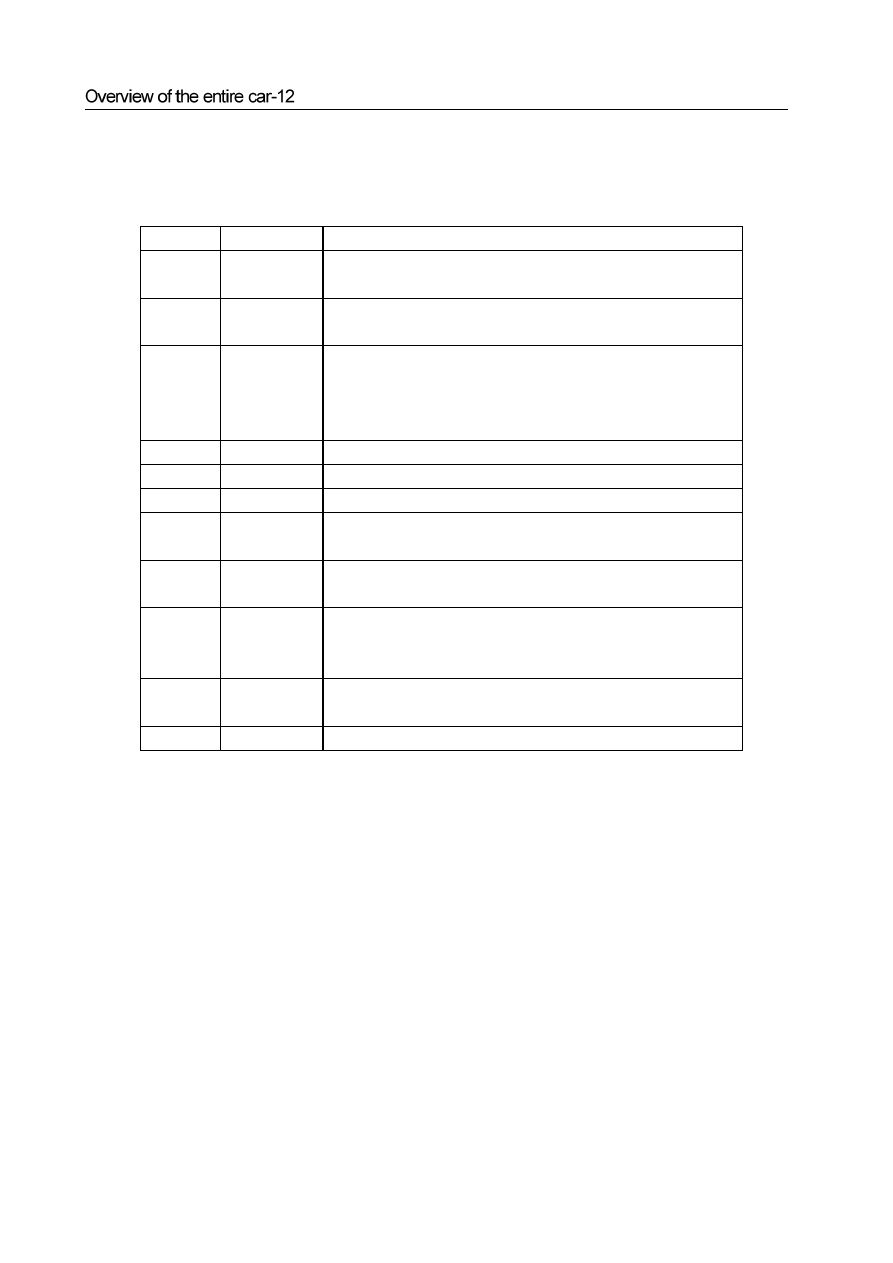
The structure and parameter of the air-conditioning system is shown in table 8.
Table 8 The structure and parameter of the air-conditioning system
Serial No.
Item
Structure and Parameter
1
Structure and
shape
Front and rear heating and cooling air conditioner, vapor compression type
cooling, hot-water heating
2
Performance and
parameters
Refrigerating capacity 3.5kW, heat exchange capacity 3.5kW, fan capacity
350m
3
/h
3
Operation
Control board button type operation, temperature auto control, air door micro
motor drive, the temperature in the car can be controlled automatically, the
fanning position mode, heating/cooling mode, air intern/external cycling mode
and wind speed and temperature can be selected and adjusted
4
Refrigerant
R134a
5
Compressor
SD7V16 variable capacity compressor, with a maximum capacity of 160ml
6
Condenser
Parallel stream mode structure, flat pipe thickness of 26mm
7
Evaporator
Two boxes structure, cascading evaporator, F expansion valve, centrifugal
blower
8
Drying fluid
collector
External diameter φ60.5mm
9
Refrigerating
pipe and
warm water pipe
Refrigerating pipe: complex structure of rubber refrigeration soft tube and
aluminum tube. The warm water pipe: rubber molding pipe
10 Transducer
Outdoor temperature sensor, indoor temperature sensor, evaporator temperature
sensor
11
pressure switch
Three-state pressure switch
Chapter 2
Fuel supply system and exhaust system
Fuel supply system :
Disassembly of the fuel tank . . . . . . . . . . . . . . . . . . 3
Installation and disassembly of the Fuel pump . . . . . . . . . . . ..4
Disassembly of the components of fuel supply system. . . . . . . . ...4
Disassembly and adjustment of the accelerator pedal operating system . . 5
Exhaust system :
Disassembly of the blast pipe assembly. . . . . . . . . . . . . . .8
Installation of the blast pipe assembly. . . . . . . . . . . . . . . 9
Нет комментариевНе стесняйтесь поделиться с нами вашим ценным мнением.
Текст