Great Wall Hover. Manual — part 2
Front shaft/axle
CC6460K wagon has the two-cross arm, independent suspension, breakaway front axle.
CC6460KY wagon has the two-cross arm, independent suspension, breakaway steering drive axle , hyperbolic gear single-stage main
reducer, plain bevel gear differential mechanism, universal drive semiaxle, Birfield ball-joint, main reduction ratio i
0
=4.55, Max. input
torque is 900N
m.
Rear axle
Non-breakaway drive axle, integral stamping-welded axle housing, hyperbolic gear single-stage main reducer, plain bevel gear differential
mechanism, semi-floating semiaxle, main reduction ratio i
0
=4.55, Max. input torque is 900N
m.
Wheel and tyre
The type, specification and main parameter of wheel and tyre see Table 4.
Table 4 Type, specification and main parameter of wheel and tyre
Transmission
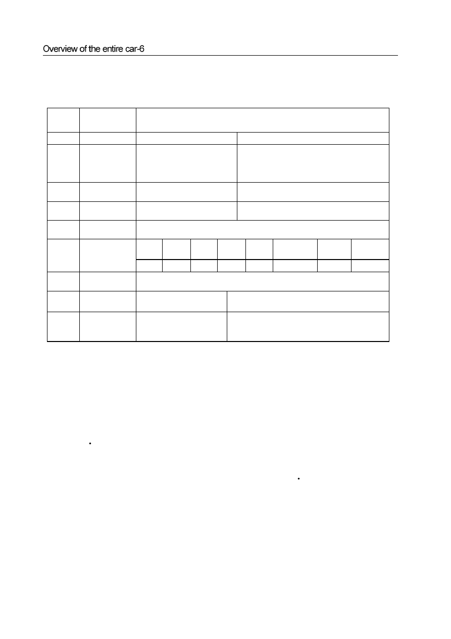
For the structure and main technical parameter of transmission see Table 3.
Table 3 Structure and main technical parameter
Serial
No.
Item Specification
and
parameter
1 Model
SC5M2D-C
SC5M4D-C
2 style
manual mechanical step
transmission of full synch, 5
forward steps, 1 reverse step, direct
manipulation
manual mechanical step transmission with torque
divider of full synch, 5 forward steps, 1 reverse step,
direct manipulation
3
Center
distance(mm)
72
72(transmission), 222.25 (torque divider)
4
Max. input torque
(N. m)
196
196
5
Max. input torque
(r/min)
5500
Step
I
Step
II
Step
III
Step
IV
Step
V
Step
R(Reverse)
Step
H(high)
Step
L(low)
6 Speed
ratio
7
Gear pair of
speedometer
8:25
8
Total net
weight(kg)
38 68(include
torque
divider)
9
Outline
dimension: L×W
×H
1070mm×466mm×
399mm( not include height of
steering level)
1070mm×460mm×380mm( not include height of
steering level)
Drive shaft
The structure of rear drive shaft assembly of CC6460K wagon is the three cross-axle universal joints, two drive shafts with extens
intermediate support free-maintenance segmental structure. The front and rear drive shaft assembly of CC6460KY wagon has the
universal joints, one drive shaft with extension spline, free-maintenance integral structure respectively.
Overview of the entire car-7
Suspension
The front suspension is the torsion bar spring, double-cylinder inflatable hydraulic damper, transverse stabilizer rod, double
cross-arm independent suspension. The distance between the center of front shaft of lower arm fixing nut and level ground is
295mm±1mm.
The rear suspension is the four-connecting rod, coil spring, double-cylinder inflatable hydraulic damper, transverse stabilizer
rod, no independent suspension.
Carriage
Peripheral trapezoidal structure; welded by two box section longitudinal beams and several box or tube section cross beams.
Steering system
Pinion-and-rack power steering-gear, hydraulic assists steering. Breakaway front steering trapezoidal structure. Diameter of
quadriradistus steering disc φ380mm, adjustable angle, power-absorbing steering pipe. For main technical parameters of
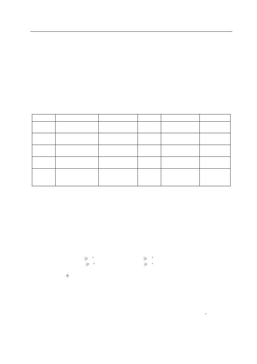
steering system refer to Table 5.
Table 5 Main technical parameter of steering system
Serial No.
Item
Parameter
Serial No.
Item
Parameter
1 wheel
camber 0°±30′ 6
Rotary round of
steering disc n
3.64
2 kingpin
inclination
12°30′±30′ 7
Angle drive ratio of
steering system i
0ω
18.2
3 kingpin
castor
3°30′±30′ 8
Force drive ratio of
steering system i
0p
198.0
4 toe
(mm)
0~2 9
Normal efficiency of
steering gear η
+
≥75%
5
Steering angle of
internal and external
wheel (°)
32/28 10
Reverse efficiency of
steering gear η
-
≥60%
1.Adjustment of .4-Wheel Alignment
Test and adjust the front wheel alignment value and adjust the toe on the 4-Wheel Alignment meter.
a. Adjustment of kingpin castor: The standard value is 3°30′±30′(adjust the difference of left and right kingpin
castor to within 30′);
b. Adjustment of toe: The toe with standard value of 0~2mm is adjusted by rotating the steering cross rod. When adjust
the toe, it should rotate the cross brace in left and right side evenly. Tighten the lock nut after adjustment, the torque is
55 - 65N·m.
c. Centering and fix of steering wheel: according to the display of the alignment gauge, turn the front wheel to right
ahead, after removing the steering wheel without changing the position of steering lever, mount the steering wheel
with center aligned, the radials of the steering wheel shall be in the bilateral symmetry position, and the symbol of
Great wall on the steering wheel shall be in the confrontation position of the driver, tighten the nut, with a tightening
torque of 25 - 35N·m.
Left wheel left steering:
32
, right wheel left steering:
28
;
Left wheel right steering:
28
, right wheel right steering:
32
;
b. Under the light condition of the car, the height between the center of front axis fixed bolt of the lower suspension arm to the
ground is 295
1mm, if the dimension is not within this scope, reach it through adjusting the torsion bar adjustment arm
bolt;
c. The reference dimension of the height of the car is : the left and right deviation is less than 10mm;
3. Checking the free gap of steering wheel:
Turn the orientation of the car to front, stop the engine, exert a force of about 4.9N on the steering wheel along the circumferential
direction to make the it turning to the left, there is resistance force, stop turning when the resistance force is growing; then turn
the steering wheel to the right, stop turning when the resistance force is felt to be growing; the radian value that the external edge
of steering wheel runs is the free gap of the steering wheel, its standard value shall be less than or equal to 20
, and the corner
from the central position to the left or right shall be no larger than 10.
Brake system
The front wheel brake is ventilation coil type, the rear wheel brake is disk and drum type. The service brake type is that the double-
loop vacuum assist hydraulic brake is applied on the front and rear disc brake. The parking brake is mechanical dragline acting on the
drum brake of the rear wheel.
The free stroke of brake pedal is 20mm
30mm, and the operating stroke of the pedal is 120mm. The operating stroke of the brake
handle is 17
(3 teeth)
30
(8 teeth).
1. The adjustment of brake pedal
Measure the operating stroke of the brake pedal, the standard value is 120mm. When the eighth is no in compliance with the
requirement, make adjustment according to the following procedures:
a. Separate the brake lamp switch wire connector, loosen the blocking nut, and turn the brake lamp switch to the position that the
stopper is not touched;
b. Unscrew the blocking nut of the operation connecting rod, use the thinnose pliers to turn the operation connecting rod, adjust
the brake pedal height to standard value, after reaching the standard value, tighten the lock nut;
c. Turn the brake lamp switch to the position that the stopper of brake pedal is just touched, continue the turning for 1/2
1 circle,
and tighten the blocking nut;
d. Connect the brake lamp switch wire connector;
e. The brake lamp should not be light when the brake pedal is in release status.
2. Standard value of brake pedal free stroke: 20-30 mm
a. Under the stopping status of the engine, step on the brake pedal for 2
3 times, clear the influence of brake assistor, then use
hand to push the brake pedal to the position that there is resistance, measure the amount of movement (free stroke). It shall
be in compliance with the regulation of standard value;
b. If the gap is less than the regulation value, check to see whether the gap between the carrier rod of brake lamp switch and the
brake pedal is in compliance with the regulation. If this gap is exceeding the regulation, it means that the gap between the drive
rod clevis pin and the brake pedal arm is exceeding the regulated value.
3. Start the engine, step down the brake pedal with a force of about 700N,ehck the main brake pump, whether there is oil
leakage on the connection positions of the brake pipeline. If there is, maintain it.
4. Operating status test of brake assistor
Conduct the operation status test of the brake assistor according to the following methods:
a. Start the engine, stop if after operating for 1
2 minutes. Step on the brake pedal for several times with normal force. Expect
that the pedal can be fully stepped down a the first stepping, the height of the brake pedal shall be raised on and on with the
stepping, thus means that the brake assistor operates normally, if the height of the pedal is not changed, it means that the brake
assistor is damaged;
b. Under the stopping status of the engine, step on the brake pedal for several times, confirms that the height of brake pedal is
elevated on and on, under the status that the brake pedal is stepped down, start the engine. At this time, the brake pedal will
move down a bit, it means that the brake assistor is working normally. If the brake pedal is moving upwards, it means that the
brake assistor is damaged;
c. Under the operation status of the engine, step down the brake pedal to stop the operation of the engine. AT this time, the there
shall be no change of the height of brake pedal within 30 seconds, it means that the brake assistor is working normally. If the
brake pedal is moving upwards, it means that the brake pedal assistor is damaged.
5. Adjustment of the parking brake system:
a.For positioning, pull the brake bar to the limit position for over 3 times, use a force of about 400N to pull the brake parking
lever, count the number of knocking teeth. The standard value of stroke of parking brake : 17
(3 teeth)
30
(8 teeth);
b.If the stroke of brake parking lever is too big and not in compliance with the requirement, adjust it with the following methods:
Loosen the brake parking lever, unscrew the adjusting nut.
Remove the adjuster hole cap from the brake assembly, use screwdriver to turn the adjustor in the arrow direction to the limit
that the brake drum cannot turn.
Rotate 5 teeth in the counter arrow direction.
Rotate the adjusting nut, adjust the brake parking lever stroke to the standard value.
c. If the stroke is less than the standard value, unscrew the adjusting nut to make it reach the standard value.
d. Check to see whether the adjusting nut and the rod are loosened, whether the adjusting nut is fixed in the fixed seat.
e. After adjustment, jack up the rear part of the car. Loosen the brake parking lever, the brake disc shall not be dragged when
checking the rear wheel.
f. The breaking in of the parking brake: use the force of about 200-250N to pull the brake parking lever,drive the car for about
400m with a speed of about 60km/h, repeat for 2-3 times, then test on the slope of 30%, the car shall be able to be parked.

Overview of the entire car-9
Car body
The structure shape and parameters of the car body is shown in table 6.
Table 6 The structure shape and parameters of the car body
Serial No.
Item
structure and parameter
1 Car
body
1.1
Structure shape of
car body
Long head two boxes five doors five seats totally metal enclosed type hard top no
carrier type car body
1.2
White car body
Punching, welding, totally metal enclosed type structure
1.3
Door assembly
Frame type, card plate type door lock, hinge type hinges, with side protection rod, four
side doors open outwards by turns, rear door open upwards. Centralized controlled
door lock, electric drive glass frame riser
1.4
Engine bonnet
Opening upwards and backwards, single arm hinge
2
Internal and external
decoration and
auxiliary
components of car
body
2.1
Internal decoration
Softening design, in compliance with the man-machine engineering and comfort ability
requirement
2.2
Meter board
Injection molding type structure, metallic framework
2.3
A, B, C pole and
inter door protection
plate
Injection molding, set with sundries box on the door protection plate
2.4
Cab handle
Metallic frame, PVC surface, PUR foaming layer in the middle
2.5 Windscreen
Panorama curved surface windscreen. Front wind window: triplex glass, with a
thickness of 4.76mm. Rear wind window: toughened glass, with electrical heating
defrosting resistance wire, with thickness of 3.5mm. Other windows: toughened
glass, with thickness of 3.5mm
2.6 Rearview
mirror
External rearview mirror: electric drive, electrical heating defrosting, anti dazzle type,
the left and right side are all convex mirror, with a radius of curvature of 1400mm. The
internal rearview mirror: manual, anti dazzle type, plane endoscope.
2.7 Seat
Pilot and co pilot seat: independent seat, front and back position, the backrest angle
and seat headrest, etc. can be adjusted. Back seat: independent seat, the backrest angle
and seat headrest, etc. can be adjusted.
2.8 Safety
belt
Back seat middle seat two points fixed type, three pointes fixed emergency blocking
mechanical safety belt for other seats.
2.9
Sun visor
Luxurious type, with lamp and cosmetic mirror
2.10 Skylight
Electric
drive
skylight
2.11
Front and rear
bumper
Overall design type, PP injection molding
Checking and commissioning of the auxiliary components of car body:
Stop the car stably, check the doors, engine cover, fuel filling port cover, meter and tools box cover, front and rear ash tray cover,
floor center console sundries box cover, CD disc conveyer (VCD disc conveyer), power socket cover, etc. they shall be reliable
and flexible during starting, opening and closing, without blocking and insufficient closing and abnormal sound;
Нет комментариевНе стесняйтесь поделиться с нами вашим ценным мнением.
Текст