Great Wall Hover. Manual — part 49
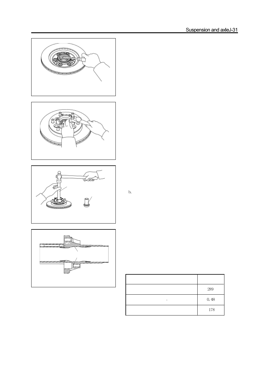
4. Remove the oil seal and inner bearing
a. Use the screwdriver to pry out the oil seal
b. Remove the inner race of inner bearing form the hub.
Check and repair of front hub
1. Check all bearings
Wash the inner race and outer race of each bearing and check them for
wear and damage.
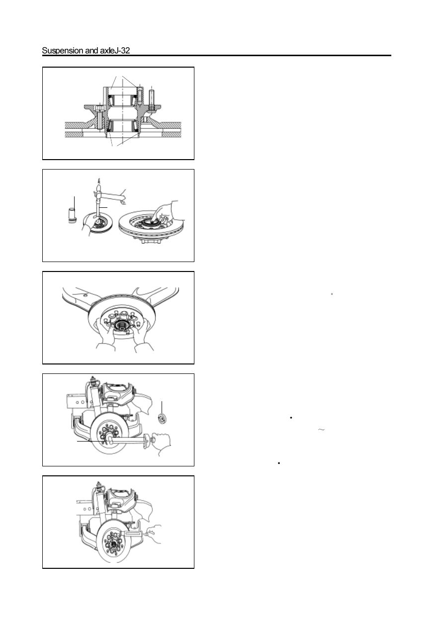
2. Replace the bearing outer race
a. Use the brass bar and hand hammer to knock out the bearing outer
race.
Use the special tools to knock in the new bearing outer race.
Assembly of front hub
1. Coat the inner surface of hub and bearing outer race
with the grease.
The grease is the Jin HP-R grease or the grease met the requirement
in following table.
special
tools
diagram of
special tools
grease
Dropping point, C
Leakage amount (104 C, 6h), g
EP performance OK value , N
Item
Typical data
2. Place in the bearing inner race; use the fill the gap
between the inner and outer race of the bearing up
with the HP-R grease.
grease
grease
3. Install the inner bearing and oil seal
a. Place the inner bearing in the hub
b. Use the special tools to knock the new oil seal into the hub.
c. Coat the oil seal lip with HP-R grease.
diagram of
special tools
special tools
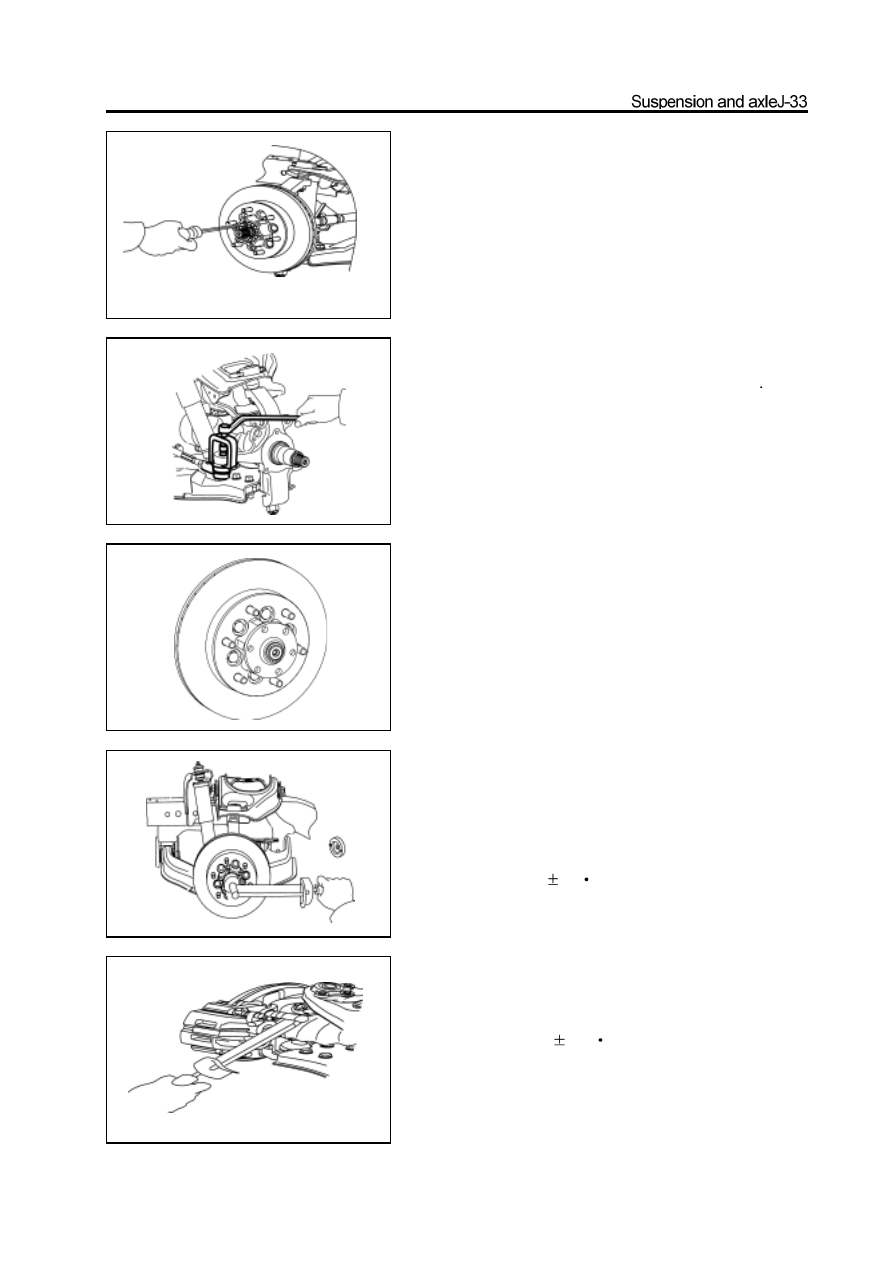
4. Install the hub on the steering knuckle
a. Install the hub on the steering knuckle
b. Install the outer bearing.
5. Adjust the pre-applied load
a. Use the special tools to screw on the locknut to specified
torque.
Tightening force: 80-100N
m
b. Rotate the hub to right and left 1/3
1/4 round respectively.
c. Screw off the nut until the nut can be loosed by hand.
d. Use the special tools to retighten the lock nut.
Tightening force: 28N
m
e. Use the spring tension meter to check the pre-applied load.
Pre-applied load (for starting): 28-56N
special
tools
diagram of
special tools
6. Install the lock washer
Install the lock washer with the surface with counterbore outwardly
and fix it on the lock nut by screw.
Remarks: If the screw installation hole on the lock washer can not
align with the screw hole on the lock nut, then it can remove the
lock washer and adjust he lock nut slightly (rotate in the direction
of Min. adjusting range ); then install the lock washer.
7. Recheck the pre-applied load
Use the spring tension meter to recheck the pre-applied load
Pre-applied load (for starting): 28-56N
If the pre-applied load does not meet the specified value, it must
remove the lock washer and adjust it by the adjusting nut.
8. Install the ring flange
a. Install the ring flange on the hub.
b. Install the adjusting washer.
c. Install the circlip.
9. Install the hub cap
a. Coat the screw of the inner hexagon bolt with the screw lock
sealant.
b. Use the inner hexagon bolt to fix the hub cap and ring flange on
the hub; tighten the bolt to the specified torque.
Tightening force: 78
5N
m
10. Install the disc brake
Install the disc brake on the steering knuckle; tighten the bolt to the
specified torque.
Tightening force: 140
10N
m
special
tools
special
tools
special
tools
Steering knuckle
Disassembly of steering knuckle
1. Remove the disc brake and front hub
(Refer to section “Front Hub”)
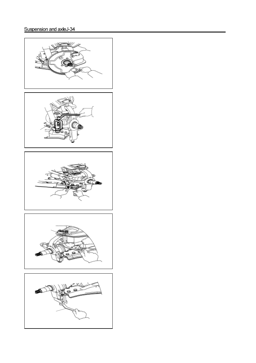
2. Remove the brake cover
3. Disconnect the steering cross rod from the steer-
ing knuckle arm
a. Remove the split pin and nut on the ball pin.
b. Use the special tools to disconnect the steering cross rod
from the steering knuckle arm.
4. Disconnect the connecting rod of stabilizer bar
from lower arm
Use the inner hexagon spanner to fix the ball pin; remove the
self-locking nut.
5. Remove the steering knuckle
a. Remove the split pin and nut on the upper ball pin
b. Use the special tools to disconnect the upper ball pin from
the steering knuckle.
c. Remove the split pin and nut on the lower ball pin.
d. Use the special tools to disconnect the upper ball pin from
the steering knuckle.
Нет комментариевНе стесняйтесь поделиться с нами вашим ценным мнением.
Текст