Great Wall Hover. Manual — part 48
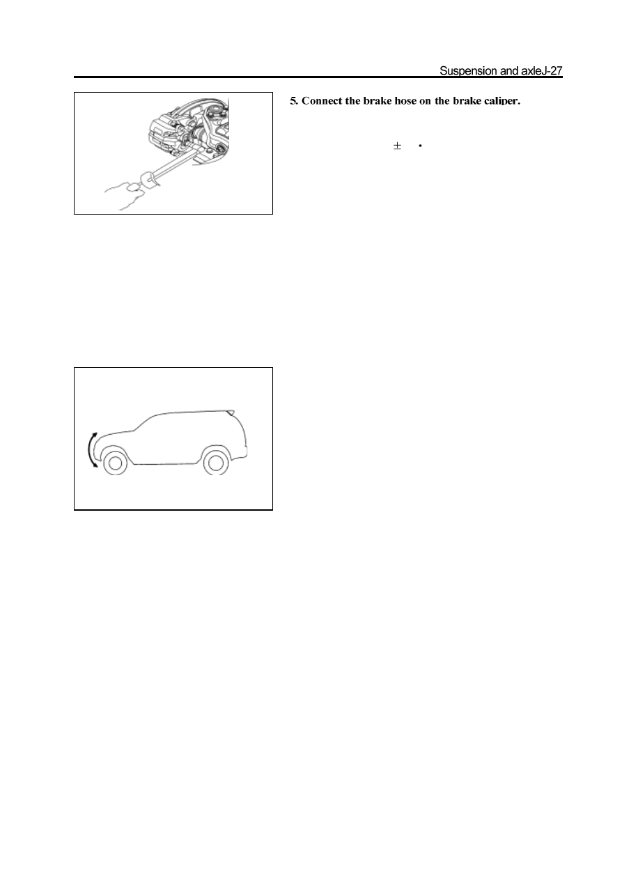
Connect the copper gasket seal and tighten the hollowbolttospecified
torque.
Tightening force: 50
5N
m
6. Discharge the air in front brake system
(refer to relevant chapter)
Remarks: It must discharge the air in the rear brake system if
disassemble the right upper arm.
7. Check the brake fluid for leakage
8. Tighten the upper arm front shaft nut to the specified
torque
Install the wheel, remove the bracket and bounce the vehicle for
several times to make the vibration damper enters into the stable
status.
9. Check the wheel alignment parameter
(Refer to 4-Wheel Alignment)
Stabilizer bar
Disassembly of stabilizer bar
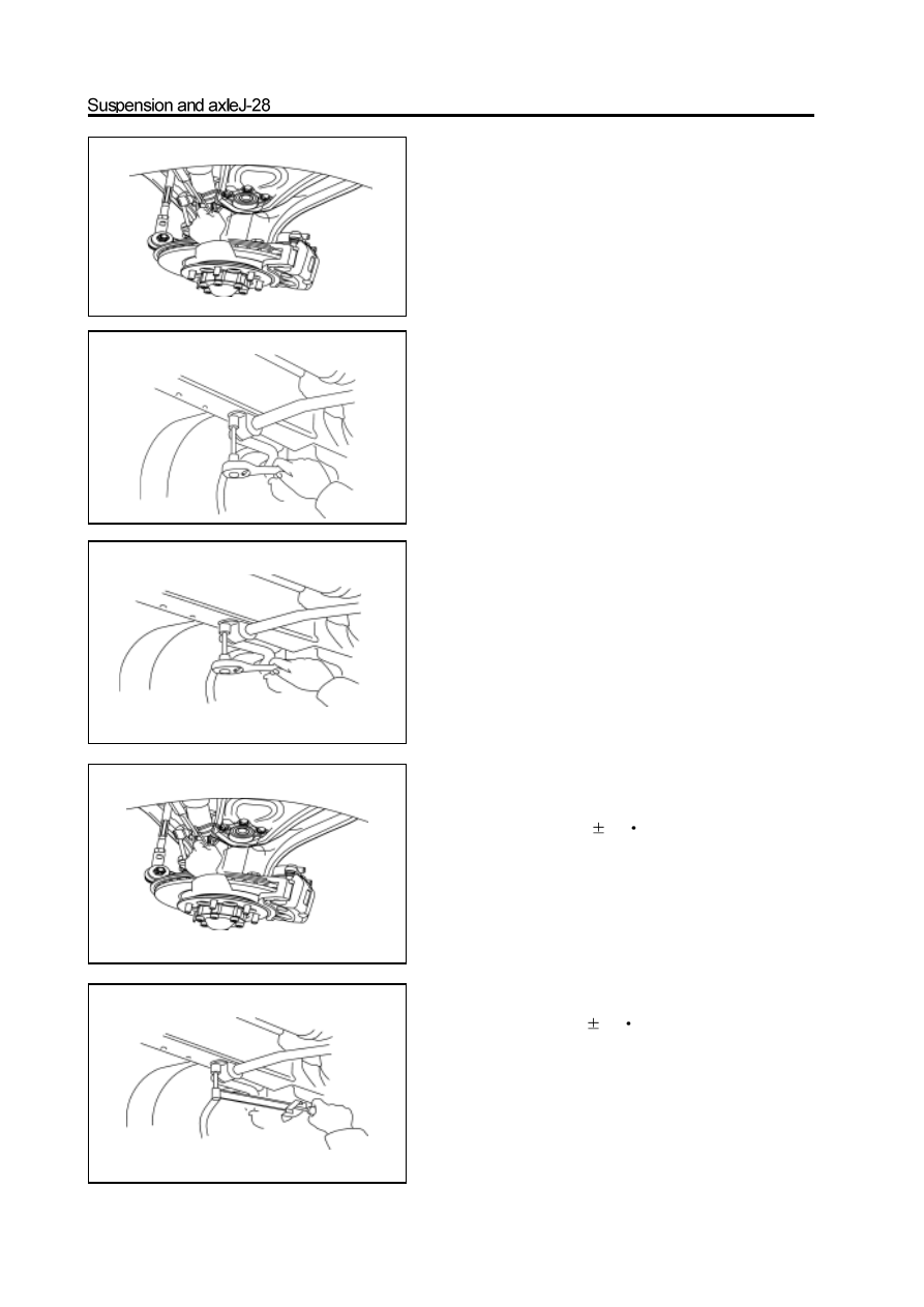
1. Disconnect the connecting bar which supports both
ends of the stabilizer bar form the stabilizer bar.
Use the inner hexagon spanner to fix the ball pin; remove the self-
locking nut.
2. Remove the bush and clip of stabilizer bar; remove
the stabilizer bar
Installation of stabilizer bar
1. Install the stabilizer bar on the carriage
Place the stabilizer bar in position; install the stabilizer bar bush
and clip on the carriage. Screw on and pretighten the bolt.
2. Connect the stabilizer bar to the connecting bar
Installand tighten the new nut to the specified torque
Tightening force: 63
5N
m
3. Tighten the clip position bolt to specified torque.
Tightening force: 23
3N
m
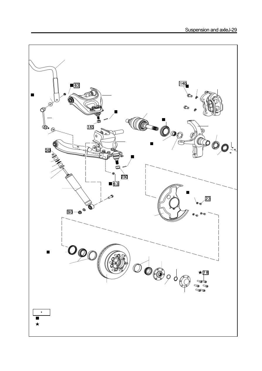
N
m: specified torque
Used component which can not be used any more.
precoated component
Front hub and steering knuckle (4WD)
stabilizer bar
flat shim
connecting rod
of stabilizer bar
hub and brake disc
flange
adjusting washer
circlip
hub cap
spring shim disc brake
split pin
lower suspen-
sion arm
split pin
upper suspension arm
drive shaft
oil seal
n e e d l e
bearing
lock washer
steering knuckle
lock nut
lock washer
screw
brake cover
spring shim
flat shim
disk shim
Shim
fill block
fill block
disk shim
oil seal
bearing
bearing
shock absorber
special tools
diagram of
special tools
Front hub
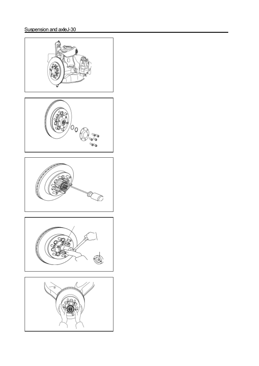
Disassembly of front hub
1. Remove the disc brake
Remove the brake caliper and hang it by steel cable.
Remarks: Do not remove the brake pipe and brake hose.
2. Remove the hub cap and flange
a. Use the inner hexagon spanner to screw off the fastening blot
and remove the hub cap.
b. Use the pliers to remove the circlip and remove the adjusting
washer.
c. Remove the flange.
3. Remove the hub and brake disc
a. Use the Philips screwdriver to screw off the tight screw;
remove the lock washer.
b. Use the special tools to remove the lock nut.
c. Remove the hub and brake disc with the outer bearing.
Нет комментариевНе стесняйтесь поделиться с нами вашим ценным мнением.
Текст