Great Wall Hover. Manual — part 11
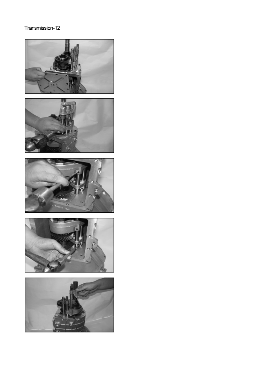
b. Remove the lower cover plate assembly
17. Remove the declutch shift shaft assembly
a. Use the punch to remove the reverse gear 5 shift fork elastic
cylindrical pin
b. Use the punch to remove the Gear 1/2 shift fork elastic cylindrical
pin
c. Use the punch to remove the Gear 3/4 shift fork cylinder pin.
d. Remove the reverse gear 5 declutch shift shaft assembly
e. Remove the gear 3/4 declutch shift shaft assembly
f. Remove the reverse gear 5 shift fork
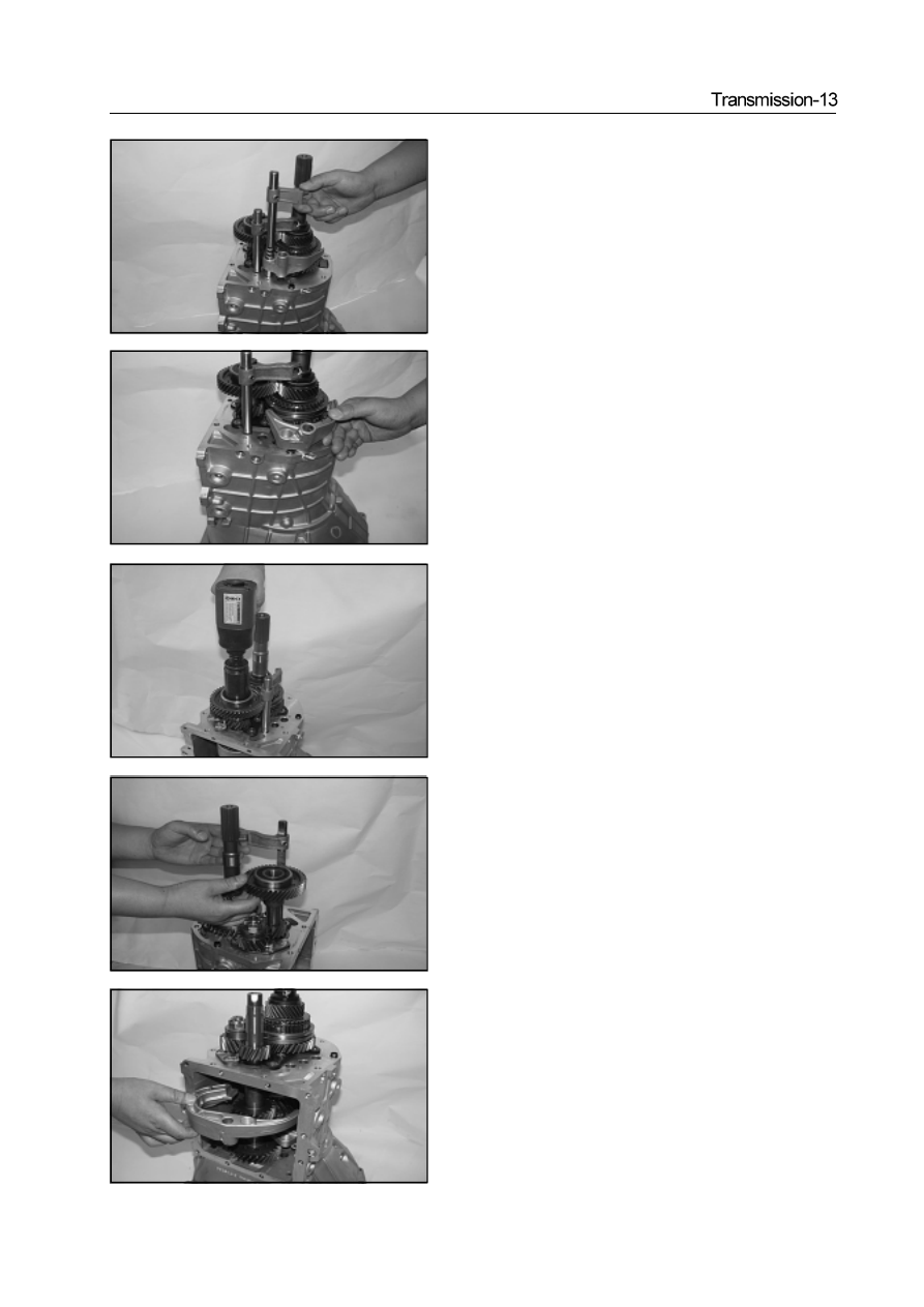
18. Remove the lock nut of intermediate shaft
Caution: When install the lock nut of intermediate shaft , the
tightening torque is 160-190N·m
19.Remove the Gear 1/2 declutch shift shaft assembly, intermediate
shaft rear ball bearing, 5th-Gear drive gear
20. Remove the Gear 1/2 shift fork
21.Use the special tools to remove the second shaft lock nut
Caution: When install the second shaft lock nut, the tightening
torque is : 250-270N·m
22.Remove the thrust plate
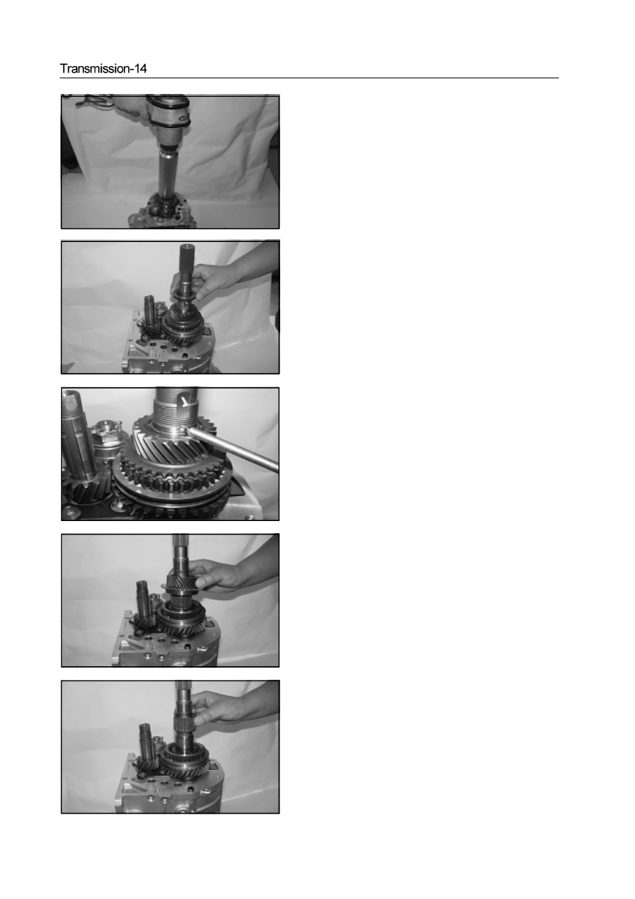
23.Use the magnetic rod to remove the steel ball.
24.Remove the 5th-Gear driven gear assembly
Caution: When install the 5th-Gear driven gear assembly, it should
use the plug gage to test the 5th-Gear driven gear assembly axial
clearance, ensure the axial clearance is within 0.170-0.284mm
25.Remove the 5th-Gear driven gear needle bearing
27. Use the pliers to remove the split pin on the reverse shaft lock
nut.
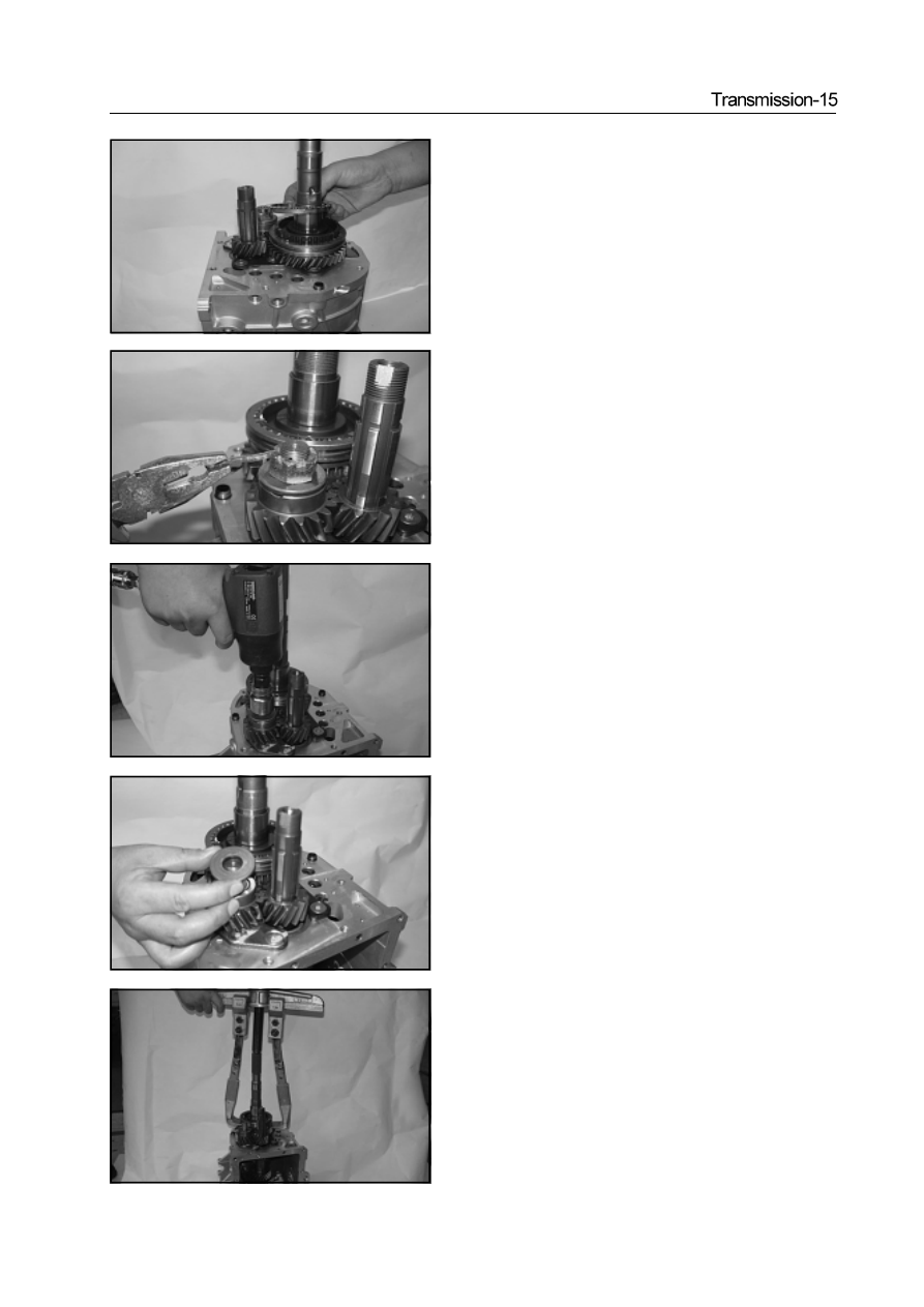
28. Use the special tools to remove the reverse lock nut
Caution: when install the reverse lock nut, the tightening torque
is within 20-60N·m
29. Remove the thrust plate
30. Remove the 5th/reverse -Gear synchronizer assembly
a. Use the special tools to remove the 5th/reverse -Gear synchronizer
assembly
26. Remove the synchronizer gear ring
Caution: When install the synchronizer gear, it should use the
plug gage to test the synchronizer gear ring axial clearance, en-
sure the axial clearance is within 1.25-1.65mm
Нет комментариевНе стесняйтесь поделиться с нами вашим ценным мнением.
Текст