Great Wall Hover. Manual — part 57
Replacement of drive gear oil seal of front reducer assembly
1. Support the front of car; remove the left and right
front wheel and the beam under the reducer.
2. Drain the lubricant oil in the front reducer; remove
the left and right steering knuckle
3. Disconnect the front reducer assembly flange from
the drive shaft and use the jack to remove the front
drive axle
Caution: Make the assembly mark on the reducer and
drive shaft before separate them.
4. Remove the front differential assembly
(Caution: Drain the oil in front differential before the
disassembly)
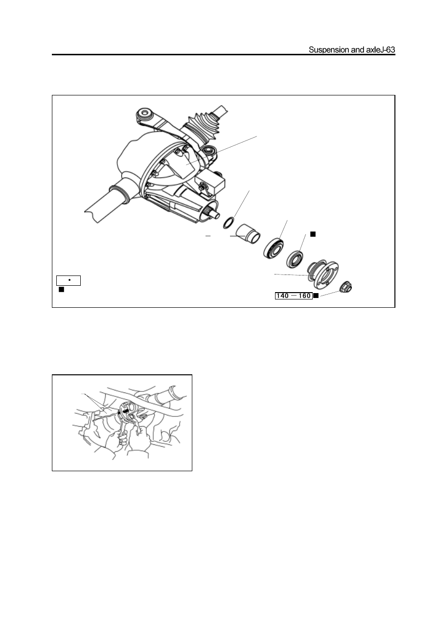
front reducer
assembly
washer
spacer
drive
bevel gear
bearing
oil seal
front reducer drive gear flange,
main gear flange and dustproof
cover assembly
Used component which can not be used
any more.
N
m:
specified torque
assembly mark
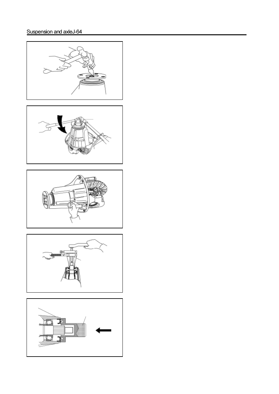
5. Remove the drive gear flange and dustproof cover
assembly
a. Use the hand hammer and chisel to loose the riveted part on
nut.
b. Use the special tools to clamp the drive gear flangeandremove
the drive gear nut.
c. Use the cooper bar to knock down the drive gear flange and
dustproof cover assembly.
6. Remove the drive gear oil seal
Use the special tools to remove the oil seal; do not
damage the inner wall of reducer housing.
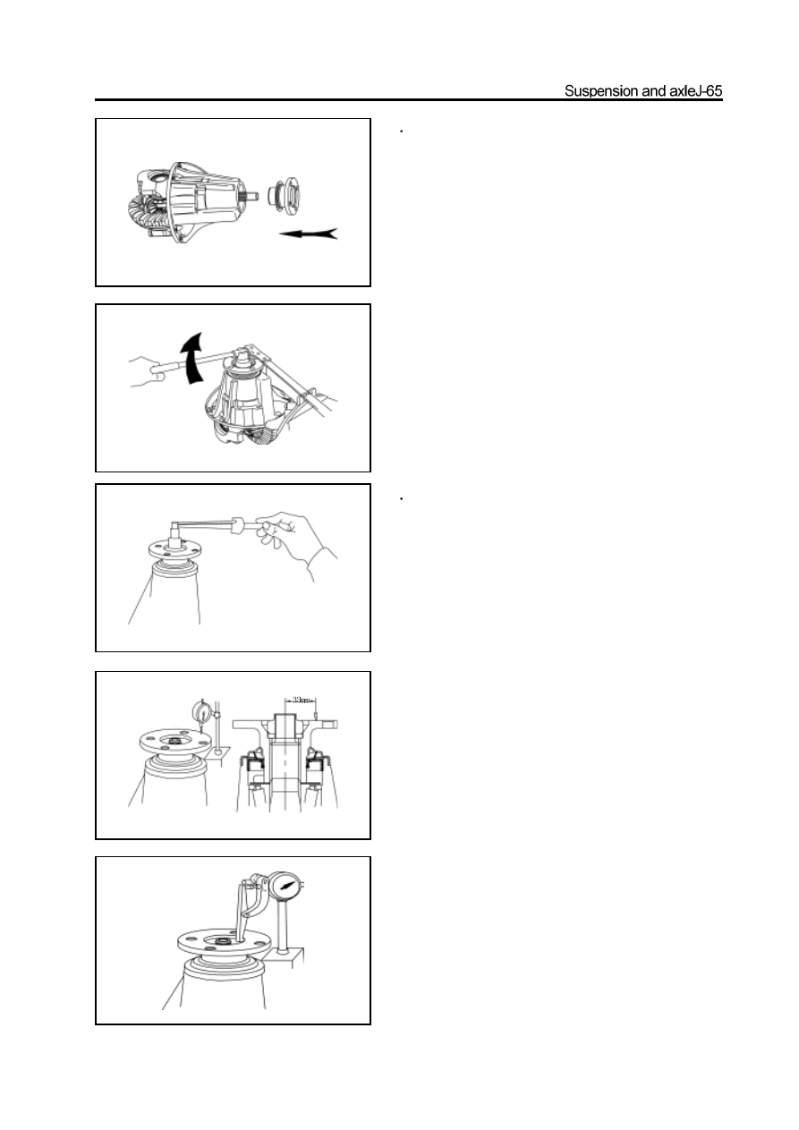
7. Install the new drive gear oil seal
a. Use the special tools to knock into the new oil seal.
b. The top of the oil seal is level to the top of reducer housing.
Caution: Coat the oil seal lip with the lithium base grease and
the oil seal should be in correct position.
special
rotate the wrench in clockwise.
special
special
8
Install the drive gear flange and dustproof cover
assembly
a. Match the drive gear flange and dustproof cover assembly on
the front drive gear.
b. Coat the new nut with the lithium base grease.
c. Use the special tools to clamp the flange and tighten the nut
to the specified torque.
Tighten torque:140-160N.m
a. Use the torque meter to measure the pre-applied load of the
gap between the drive bevel gear and driven bevel gear.
pre-applied load: 1.2-1.7N.m
b. Is should be replaced by the thicker washer if the pre-ap
plied load is more than specified value
(The step of thickness of washer is 0.03mm)
c. Is should be replaced by the thinner washer if the pre-applied
load is less than specified value. Repeat the previous
operation until meet the requirement.
Caution: Do not reduce the load by loosing the nut.
10. Check the axial and radial run-out tolerance
offlange.
a. Use the dial indicator to measure the axial runout of flange.
Max. axial runout: 0.1mm
b. The max. radial run-out tolerance is 0.1mm
It should check the bearing if the radial run-out tolerance is large.
9
Adjust the pre-applied load of the drive
bevelgear bearing
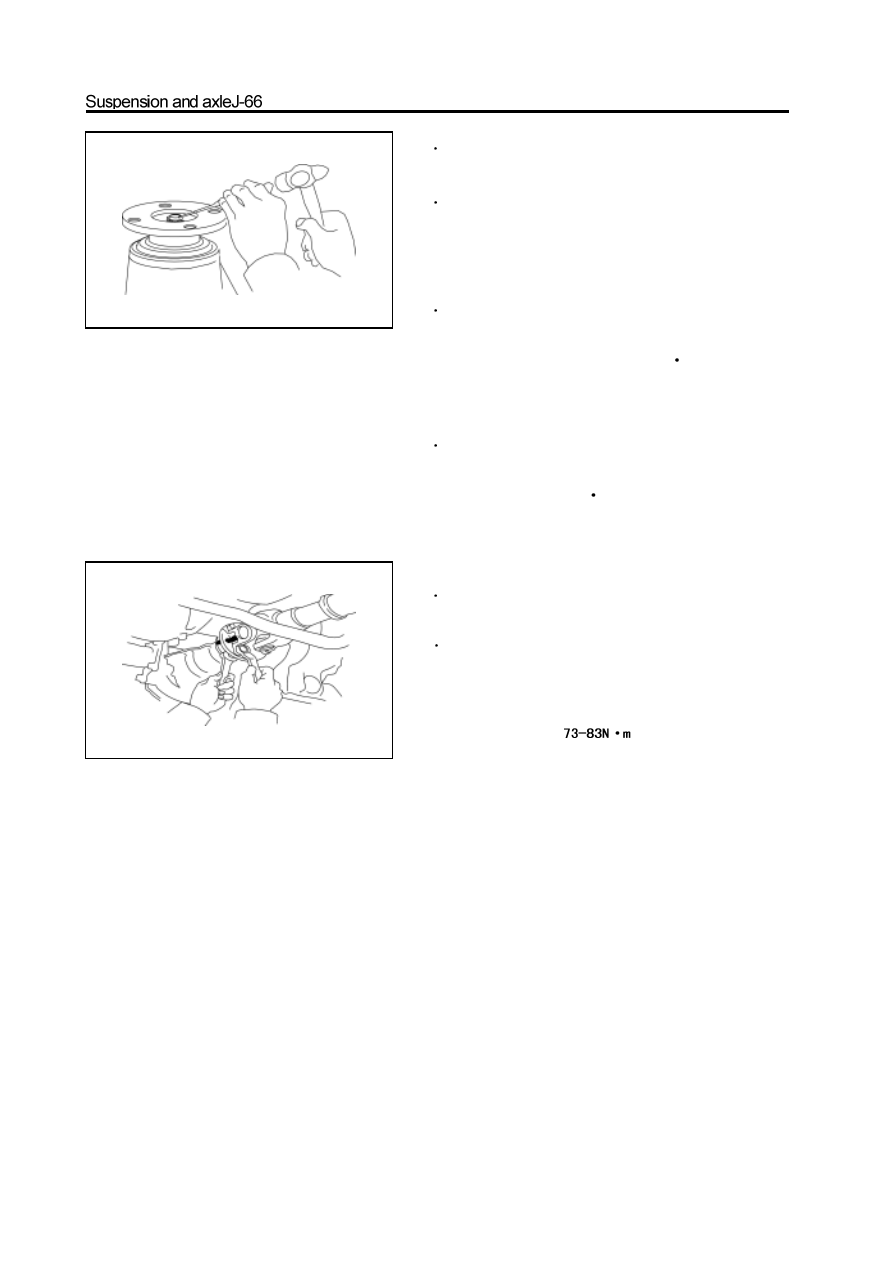
11
Rivet the drive gear nut after meet the previ-
ous requirements.
12
Install the reducer assembly on the front drive
axle assembly and assemble the front drive shaft
assembly (refer to Assembly of Front Reducer Assembly
and Assembly of Front Drive Shaft Assembly)
13
Install the oil drain plug; screw off the oil
filling plug and filled with the hypoid gear oil.
Tightening force of oil drain plug: 30-35N
m
Model of lubrication oil: GL-5
Filling amount: Flush to the lower edge of oil filling open
14
Insert the oil filling plug washer and tighten
the oil filling plug to the specified torque.
Specified torque : 140-150N
m
15
Install the front drive axle assembly on the
carriage.
16
Connect the drive shaft to the flange
a. Align the assembly mark; use four bolts and nuts to connect
the flange of drive shaft and front drive axle.
b.Tighten the nut to the specified torque.
specified torque:
Remarks: Keep the clean of the field during the maintenance.
Нет комментариевНе стесняйтесь поделиться с нами вашим ценным мнением.
Текст