Great Wall Socool (2006 year). Service Manual — part 6
TF-20
1
convex plate
groove
2
3
4
5
6
1
2
3
4
5
6
7
1. electric shift convex plate
2. torsion spring
3. shift shaft
4. gear down shift fork assembly
5. shift fork
6. gear shifting shaft
Transfer Box
Transfer Box Assembly
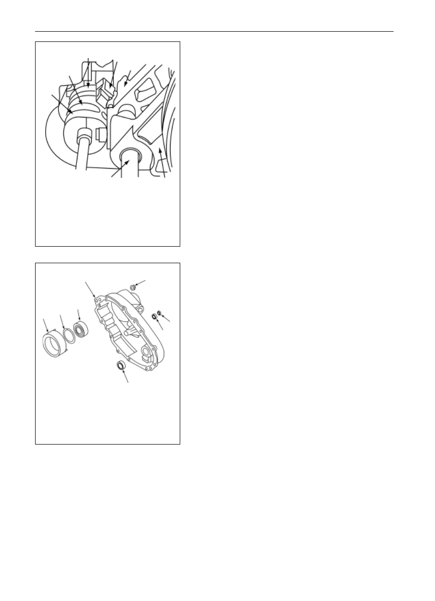
1. clutch washer assembly
2. snapping ring
3. ball bearing
4. transfer box rear body
5. nut
6. oil seal
7. bearing
8. needle bearing
11. Rear cover Assembly
Mount the parts into the rear cover according to the following
process:
(a)
Locate the rear cover on the suitable press machine, the
coupling face of the rear cover shall face upward and
parallel with the work face of the press machine.
(b)
Locate the needle bearing, of which the marked end
facing upward, and press it in the rear cover until the
upper end of needle bearing is 40.47
40.97 lower than
the coupling face of the rear cover that matches with the
front housing.
(c)
Press the ball bearing in the rear cover and mount the
snapping ring well.
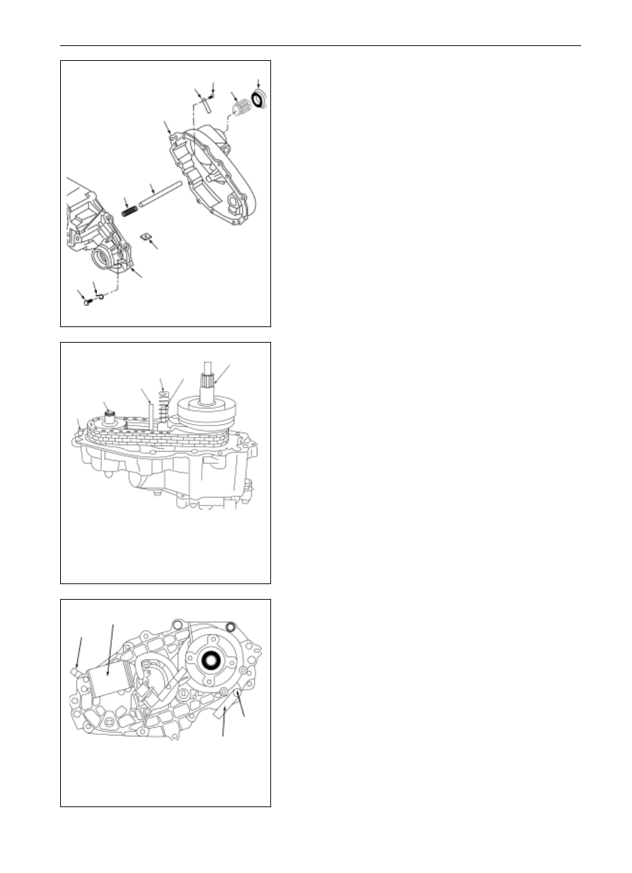
(d)
As for the electric shift transfer box, the parts shall be
encased according to the following process:
(1)
Confirm the four O-rings are set on the clutch
washer assembly (one O-ring is located on the coil,
the other three on studs).
Mount on the clutch coil assembly, of which the
wire and stud shall protrude out the rear cover, take
notice not to damage the wire when screwing up the
nuts.
Fastening torque
(811)Nm
(2)
Encase the motor bearing and oil seal in the rear
cover.
(e)
As for the electric shift transfer box, encase the as-
sembled electric shifting cam group and clutch shell in
the process as follows:
(1) Put down the electric shifting cam group as shown in
the drawing.
(2) Hold the shift guide shaft downward and raise lightly
the toggle fork assembly. Run the electric shifting
cam group in place, so that the contact roller on
deceleration toggle fork assembly enters in the groove
of shifting cam, and the projecting part of lock
toggle fork is at the rear end of the shifting cam, and
then take reduce the component elements in the
transfer box housing, meanwhile, joint the shift
shaft on the pin in transfer box housing.
(3) Locate the clutch shell well through the shift exter-
nal gear sleeve and mount on the snapping ring.
8
-------------------------------------------------------------------------------------------------------------------------------------------------------------
TF-21
Q
R
N
O
P
NM
S
T
N
U
V
N
O
P
Q
R
S
(d)
All of the following aligning conditions shall be satisfied
when the rear cover assembly is mounted on the transfer
box front housing:
a)
Align the pin hole in the rear cover to the pin on the
housing.
b)
Align the rear output shaft to the inner bearing in
cover rear hole.
c)
Align the blind hole in the rear cover and the shift
guide shaft; ensure the return spring is not tilted.
Check the hole in velocity sensor of the rear cover
with a pen.
d)
Align the shift shaft and the inner bearing in rear
cover.
(e)
Screw up the nine bolts after locating the sign bolts
correctly.
(f)
Encase the gear of odometer in the rear cover assembly
through the spline of the rear output shaft.
(g)
Press the new oil seal in the cover assembly
N
O
P
Q
Transfer Box
Transfer Box Assembly
1. bolt
2. wire harness
3. magnet
4. return spring
5. shift guide shaft
6. transfer box rear
body assembly
7. sign board
8. driving gear of Odometer
9. oil seal
10. transfer box front housing
1. locating pin
2. output shaft
3. shift shaft
4. return spring
5. shift guide shaft
6. output shaft.
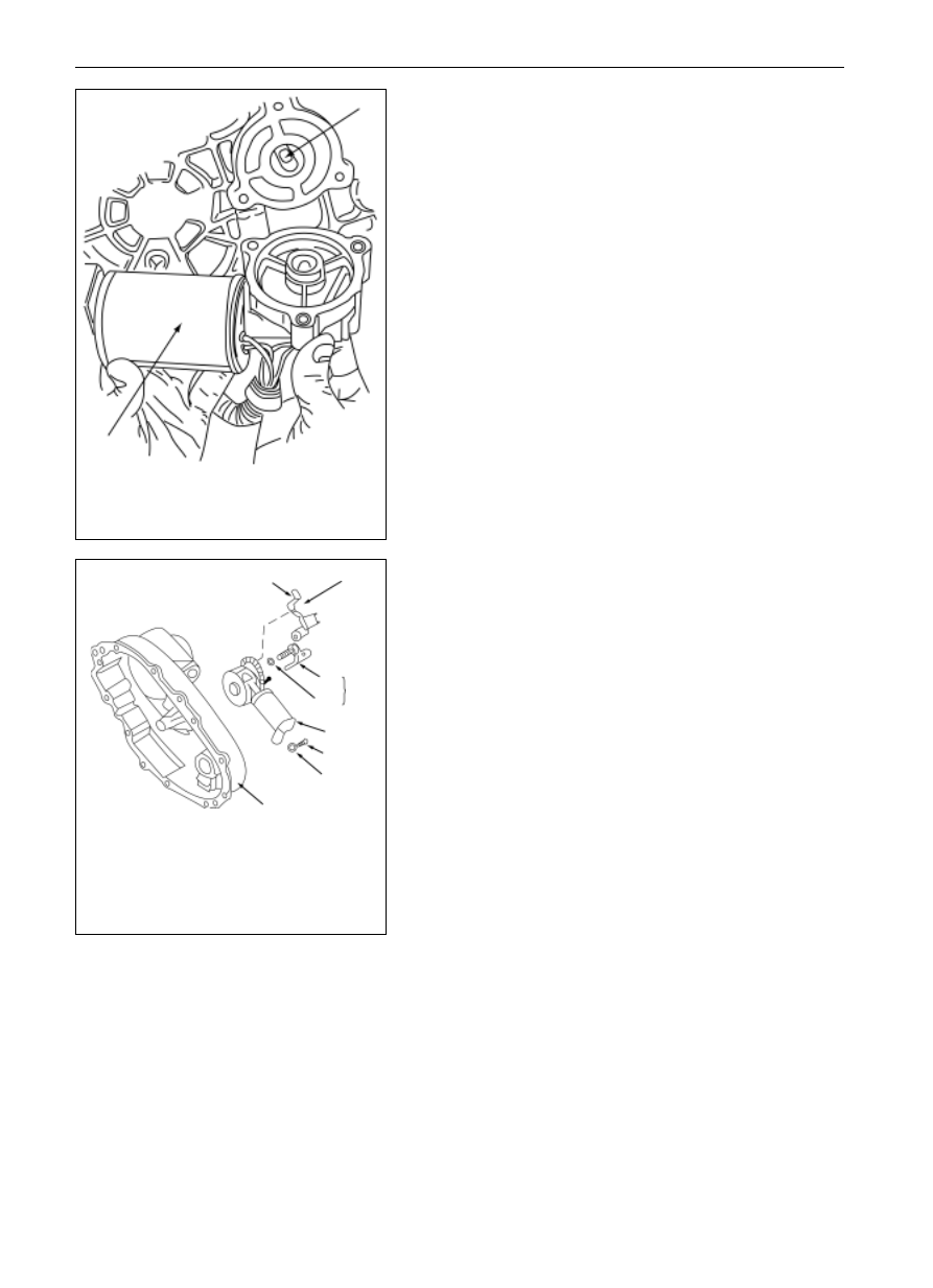
12.
Assembly of Rear Cover
Mount the aforesaid accomplished cover assembly on the
transfer box housing according to the following process:
(a)
Mount the return spring on the shift guide shaft of the
transfer box.
(b)
Mount the magnet in the groove of the housing.
(c)
Coat the Letai glue 598 of 1.6mm on the coupling face of
housing, steer clear of the screwed hole when coating
continuously.
Notice: try to button the rear cover on the transfer box front
housing with the moderate force during the following process.
Not too much force is required when mounting the rear cover
on the front housing when all aligning conditions are satisfied,
in case the rear cover cannot be mounted on the front housing,
take down the rear cover assembly to check the aligning
condition
1. wire harness clip
2. motor assembly
3. bolt
4. sign board
-------------------------------------------------------------------------------------------------------------------------------------------------------------
TF-22
1
2
3
4
6
7
8
9
5
2
1
Transfer Box
Transfer Box Assembly
1. motor assembly
2. shift shaft
1. fixed sensor bracket
2. bolt
3. sensor assembly
4. velocity sensor
5. o-ring
6. motor assembly
7. bolt
8. gasket
9. transfer box rear body
12. Mount the external electric shifting element (for the elec-
tric shift transfer box)
(a)
Locate the motor assembly by aligning the triangle
groove on motor to the shift shaft.
(b)
Move the motor to combine the shift shaft and keep it
close to the rear cover. Then run the motor clockwise
until the motor locates the correct place and the mooting
holes are aligned.
(c)
Mount the O-ring on the velocity sensor and encase the
velocity sensor assembly in rear cover. A clip and three
bolts shall be mounted on the velocity sensor.
Fastening torque
(811)Nm
(d)
Mount the bolts and gaskets on the end of motor clip.
Fastening torque
(811)Nm
-------------------------------------------------------------------------------------------------------------------------------------------------------------
TF-23
5
4
3
1
6
2
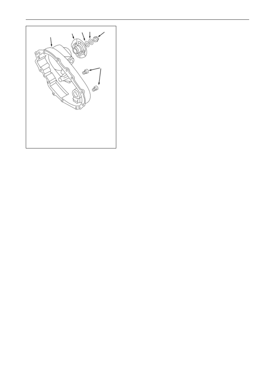
Transfer Box
Transfer Box Assembly
1. transfer box rear body
2. flange
3. oil seal
4. gasket
5. nut
6. oil plug
13. Flange assembly
The parts mount process is as follows:
(a)
Encase the two oil plugs in the rear cover.
(b)
Encase the flange, sealing ring and gasket, and then
screw up the nuts.
Fastening torque
(203244)Nm
-------------------------------------------------------------------------------------------------------------------------------------------------------------
TF-24
Transfer Box
Washing, Checking, Up-Keeping and Exchanging (Washing)
1.
Washing
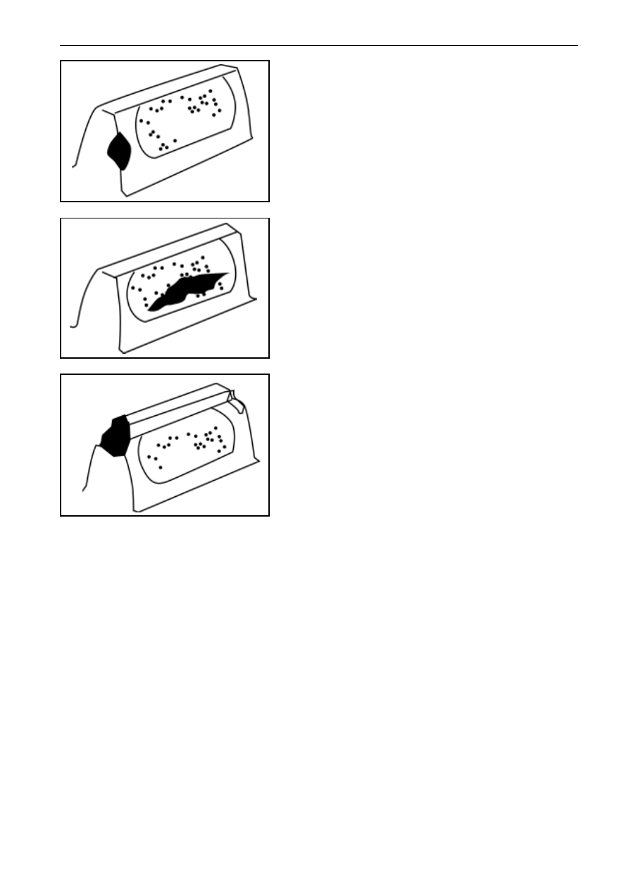
Notice: check the metal rag around the magnet first before washing, large granule or irregular metal
granule shows the disintegratation or similar damage. Small or fine metal granule shows the uneven
or serious wear. If the metal rag is founded, notice shall be taken on damage and wear inspection
during checking the rotating parts and the element matched with the rotating parts.
(a)
Common washing
Wash the parts in cleaning agent to clean away the old lubricant and deposit. Clean away the deposit in oil hole
with brush. Take notice not to scrape the metal coupling face when washing the parts cannot be cleaned with
brush.
(b)
Dry the washed parts by blowing
Dry the washed parts by blowing the low-pressure compressed air (max pressure is 137.9kPa), because cloth
thread may be left during cleaning the parts with cloth. The bearing shall be held by hand to prevent it from
rotating when blowing it.
(c)
Bearing lubrication
The ball bearing and needle bearing shall be lubricated with the lubricant for transfer box after washing. As
the non-lubricated bearing may cause damage when be dry. Cover the lubricated bearing to prevent dust
entering in.
Washing, Inspection, Maintenance or Change
-------------------------------------------------------------------------------------------------------------------------------------------------------------
TF-25
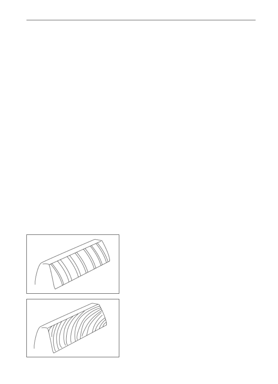
(b)
Normal gear grinding trace.
Transfer Box
Washing, Checking, Up-Keeping and Exchanging (Checking)
Checking
1.
Common Checking process
Check all parts by visual check to see whether there is damage
or serious or uneven wear (parts needed be substituted by new
parts such as O-ring, oil seal and etc. shall be excluded).
Abandon the damaged or weary parts that will affect on their
performance. The check items are as follows:
Burr: tips protruded from the material regionally
Rag: broken small blocks or particles
Crack: surface thread showing the material is partly or
completely separated.
Excessive abrasionRefer to the serious or obvious abra-
sion beyond of application limit.
Reduction changeMaterial slip caused by the heavy
pressure on part of it.
adhesive bondingGranules of the soft metal are dis-
persed and bonded on the hard metal surface.
Ditch trance: partial crack or trough that means the material
transfer instead of material loss.
Pitting corrosionDamages to the metal surface caused by
pressure, which are displayed due to color change caused
by heat generated by metal friction.
Step weara weary step may be seen or felled between the
neighboring interface or between the non-touching face
due to the excessive wear.
Uneven wear: Partially, unevenly distributed wear, which
includes holes, bright spots, uneven polishing or other
visual drawbacks.
2.
Gear or Chain sprocket tooth inspection
Check the gear and chain sprocket tooth according to the
following process:
(a)
Normal gear shaving trace.
normal gear shaving trace
normal gear grinding trace
-------------------------------------------------------------------------------------------------------------------------------------------------------------
TF-26
Transfer Box
Washing, Checking, Up-Keeping and Exchanging (Checking)
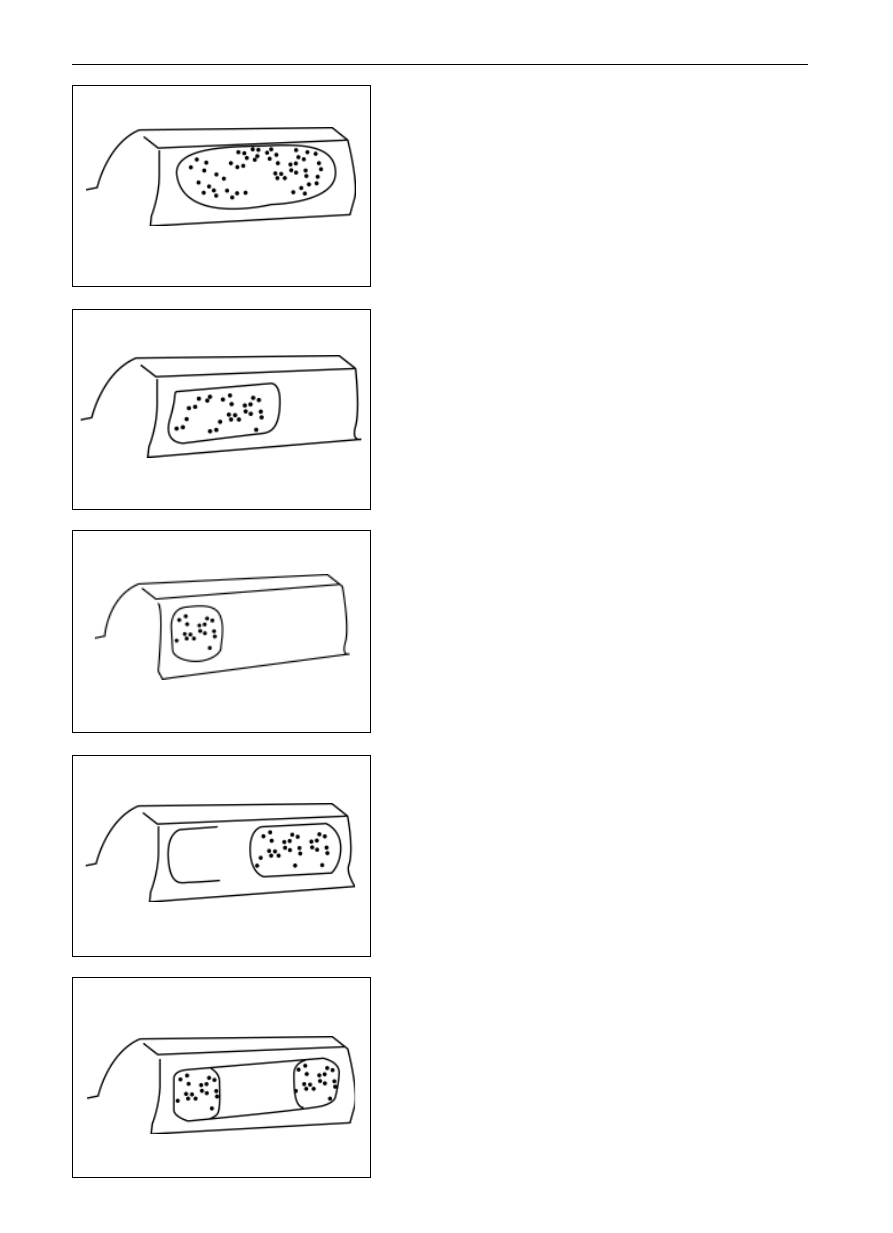
(e)
Unacceptable side deflective contact area that must be
changed.
(f)
Acceptable side-deflective contact area
(g)
Unacceptable side deflective contact area that must be
changed.
(c)
Ideal engagement contact area
(d)
Acceptable side-deflective contact area
-------------------------------------------------------------------------------------------------------------------------------------------------------------
TF-27
Transfer Box
Washing, Checking, Up-Keeping and Exchanging (Checking)
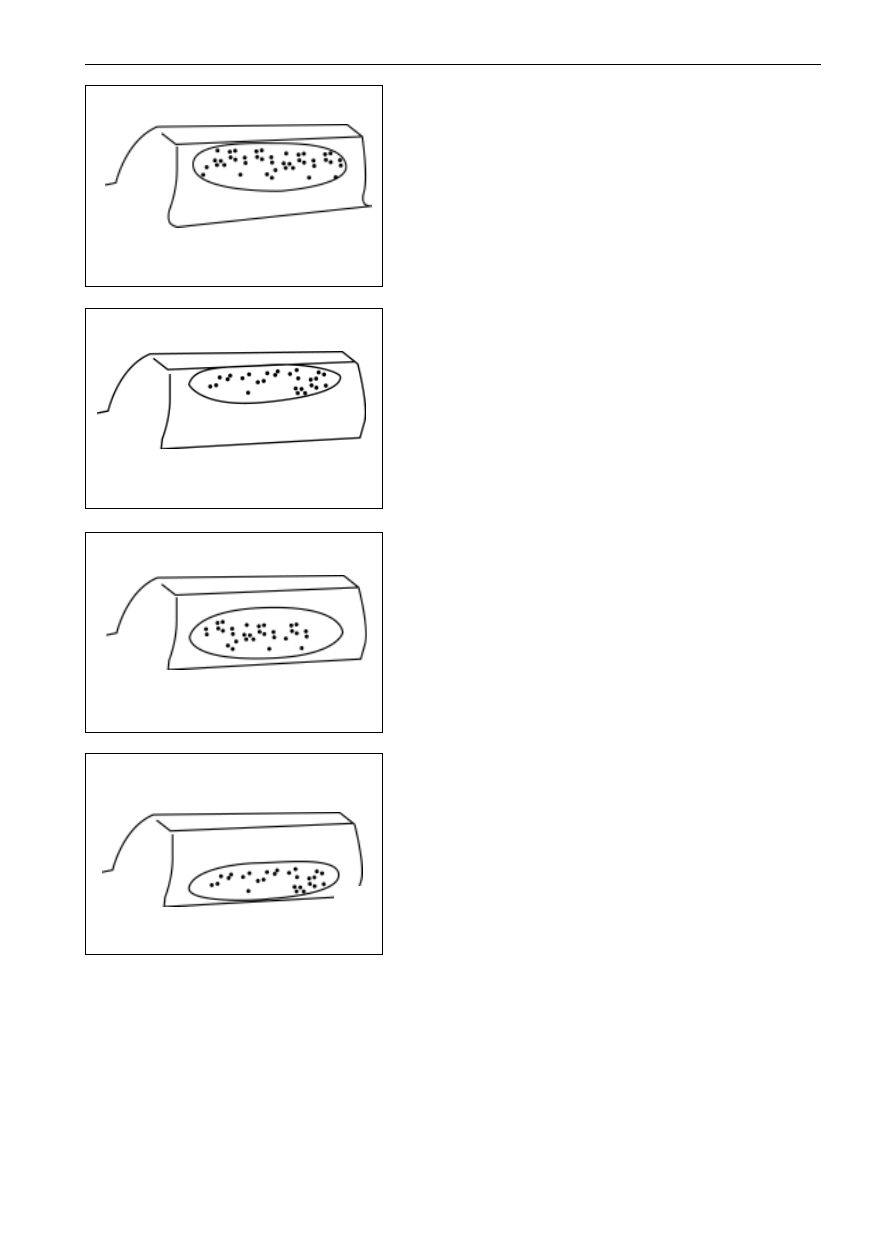
(h)
Acceptable contact area deflecting to the tooth top.
(i)
Unacceptable contact area deflecting to the tooth top,
which must be changed.
(j)
Acceptable contact area deflecting to tooth root.
(k)
Unacceptable contact area deflecting to tooth root, which
must be changed.
4.
Key tooth inspection
Check the broken or peeled spline teeth. The spline teeth may,
if only small part is peeled off, be repaired in the same way as
that for the gear teeth, and can be reused. In case the spline
tooth is broken, the spline must be abandoned. The contact
type of spline is not the same as that for gear; however, spline
that shows step sliding must be abandoned.
-------------------------------------------------------------------------------------------------------------------------------------------------------------
TF-28
Transfer Box
Washing, Checking, Up-Keeping and Exchanging (Maintenance or Change of Gear or Chain Sprocket Gear)
Maintenance or Change of Gear or Chain
Sprocket Gear
1.
Maintenance principle
(a) Conduct the maintenance for the partial, small peel off
with the suitable manual high-speed grinding tool.
(b) Do not clear away the metal as can as possible when
grinding the matrix metal.
(c) All pointed angles and sides must be repaired as the slip-
pery contour line. Because the pointed angle or edges
may be peeled off again or developed into crack.
(d) Clear away the burr with the suitable grinding stone. Take
notice not to damage the matrix when clearing away the
projecting materials, and
(e) When substituting the non-repaired parts (such as
bearing), if the part is doubted in its re-application
capability, it must be changed.
2.
Cases for gear or chain sprocket maintenance or substi-
tuting
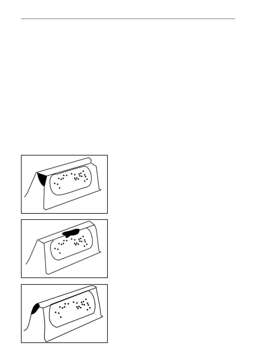
(a)
The gear, being peeled off at the two sides of tooth top in
contact face, may be repaired for reuse.
(b)
The gear, being peeled off at the central tooth top of
contact face, may be repaired for reuse.
(c)
The gear, being peeled off at one side of the non-contact
face, may be repaired for reuse.
-------------------------------------------------------------------------------------------------------------------------------------------------------------
TF-29
Transfer Box
Washing, Checking, Up-Keeping and Exchanging (Maintenance or Change of Gear or Chain Sprocket Gear)
(d)
The gear, being peeled off at the center of one side of
contact face, may be repaired for reuse
(e)
The gear, being peeled off in the center of contact area,
shall be changed.
(f)
The gear, being peeled off at two sides of tooth top, shall
be changed.
-------------------------------------------------------------------------------------------------------------------------------------------------------------

TF-30
Transfer Box
Washing, Checking, Up-Keeping and Exchanging (Attachment for Inspection Maintenance or Change of Parts)
Change the parts and fittings as requirement
Attachment for Inspection Maintenance or Change of Parts
Checking items
Acceptance/Refusal
Parts (items)
All parts (including
all springs)
Crack inspection, distortion inspection and ero-
sion inspection
All parts with crack, all parts that are bended,
distorted or poor in round bouncing are refused.
All threaded parts
Thread inspection for buckle missing or other
damage
Those parts cannot be threaded or bottomed in
overlap manner shall be refused.
F l a n g e a n d f o r k
flange
Please refer to the paragraph of
inspection to
check the spline.
Please refer to the
inspection paragraph for
spline inspection.
Velocity sensor, mo-
tor assembly
Parts of electric clutch
system
Please refer to the part of electric appliance
Sliding bearing
Inside surface inspection for the sliding bearing
In the case that the bearing has pitting corrosion
or other damage, refuse it.
Ball bearing
Check visually the ball and track of the ball
bearing to see whether there is damage such as
adhesive bonding, pitting corrosion, etc.
Ensure that the bearing are all lubricated, run the
outer race of the bearing while holding the inner
one to feel whether there is poor running or
corrosion, the bearing shall be run smoothly
without excessive clearance.
Refuse to use the damaged bearing;
Refuse to use the damaged or loose bearing; or
Check the axial clearance to see whether it
exceeds 0.23mm.
Needle bearing
Check the bearing needle roller and track to see
whether there is damage such as adhesive
bonding, pitting corrosion, etc.
Refuse to use the damaged bearing.
The rear cover, front
body and front hous-
ing of transfer box
Check to see whether there is burr on the cou-
pling face or other damage that impedes assem-
bling or sealing.
Clear away the burr according to the paragraph
of
inspection, otherwise, change the dam-
aged element
Rear cover of trans-
fer box
Check the bearing hole
Refuse to use the assembly that has pitting
corrosion
Odometer gear
Check the gear teeth referring to the Inspection
Paragraph
Refer to the gear or chain sprocket inspection in
inspection paragraph.
Clutch shell, joint
outer gear sleeve and
joint cover
Check the spline according to the Inspection
paragraph
Refer to the spline inspection of
inspection
paragraph
Locking sleeve
Check the wear or damage of the toggle fork
groove
Refuse the parts with step slipping or damage.
Shift guide shaft
Check the deformation situation
Check the burr or other damage on outer race
Check the wear of outer race
Refuse to use the bend shaft; clear away the burr
according to the
inspection paragraph, oth-
erwise refuse to use.
Refuse to use the shaft with step slipping or
other damage.
Shift toggle fork
Check whether there is wear or damage at the
location where the toggle fork combines with
the shifting cam and gear sleeve.
If any step slipping or damage is found, refuse
to use it.
-------------------------------------------------------------------------------------------------------------------------------------------------------------

TF-31
Transfer Box
Washing, Checking, Up-Keeping and Exchanging (Attachment for Inspection Maintenance or Change of Parts)
Attachment for Inspection Maintenance or Change of Parts
Parts (items)
Checking items
Acceptance/Refusal
Shift toggle fork as-
sembly
Check the wear and damage of the inserted face
that is combined with gear sleeve;
Check to see whether the contact roller can
rotate freely or is damaged or not
If any step wear or damage is found, the inserted
face shall be refused to use.
If the contact runs difficultly or is damaged, a
new pin-contact roller and new cage assembly
shall be used.
Driving and driven
chain sprocket
C h e c k t h e s p r o c k e t t e e t h a c c o r d i n g t o
the
inspection paragraph
Refer to the sprocket teeth inspection of
inspection paragraph
Shift toggle fork as-
sembly
Check the inner diameter that matches with the
output shaft
If any pitting corrosion or damage is found,
refuse to use it.
Driving chain
Check the step sliding, looseness or damage of
pin or connecting element
Refuse to use the weary or damaged driving
chain
Filtering screen
Check to see the filtering screen is clean or with
small hole or damage
Clean it where necessary, and abandon the dam-
aged one.
-------------------------------------------------------------------------------------------------------------------------------------------------------------

TF-32
Transfer Box
Washing, Checking, Up-Keeping and Exchanging (Attachment for Inspection
Maintenance or Change of Parts
Pump shell
Check to see whether there is pitting corrosion
or step slipping
Abandon it in case it is seriously damaged or
worn
Output shaft
Check the spline, check the surface that matches
with bearing and check the distortion according
to
inspection paragraph
Refer to the spline inspection of
inspection
paragraph;
Refuse to use the one with pitting corrosion or
damage;
Refuse to use the one that is bending or poor in
round bouncing.
Deceleration hub
Check the spline of chain sprocket and check the
wear or damage of the location where matches
with the toggle fork according to the
inspection paragraph
Refer to the spline inspection of
inspection
paragraph; refuse to use the one with step slid-
ing or damage.
Front output shaft
Check the surface where matches with the
bearing;
Check the spline according to the
inspection:
paragraph
Refuse to use the one with pitting corrosion or
damage
Input shaft
Check the spline according to the
inspection
paragraph
Check the distortion
Refer to the spline inspection of
inspection
paragraph;
Refuse the one that is bending or poor in round
bouncing.
Thrust washer and
thrust disc
Check the pitting corrosion
Refuse to use the one with pitting corrosion or
damage
Sun wheel
Check the gear teeth and spline according to the
inspection paragraph
Refer to the gear teeth inspection and spline
inspection of
inspection paragraph.
Planetary mechanism
assembly
Check the gear teeth according to the
inspection paragraph;
Check the wear and looseness of the planetary
gear pin; check the wear of thrust gasket
R e f e r t o t h e g e a r t e e t h i n s p e c t i o n o f
inspection paragraph;
If any step sliding or pitting corrosion is found,
refuse to use it
Electric shifting cam
Check to see whether there is step slipping or
pitting corrosion
If any step sliding or pitting corrosion is found,
refuse to use it
Shift guide shaft
Check to see whether there is step slipping or
pitting corrosion
Check the distortion situation
If any step sliding or pitting corrosion is found,
refuse to use it
Refuse to use the bending one
Planetary gear ring
Check the match performance of it with the
transfer box housing
Check the gear teeth according to the
inspection paragraph
Check the transfer box housing assembly to see
whether the gear ring is loose or not in the
housing
R e f e r t o t h e g e a r t e e t h i n s p e c t i o n o f
inspection paragraph
Transfer box housing
Check the holes matches with the bearing
Abandon the one with pitting corrosion or
damage.
-------------------------------------------------------------------------------------------------------------------------------------------------------------
PR-1
Drive shaft
page
Notice . . . . . . . . . . . . . . . . . . .. PR-2
Troubleshooting . . . . . . . . . . . . . . .. PR-2
Drive shaft . . . . . . . . . . . . . . . . ... PR-3
PR
-------------------------------------------------------------------------------------------------------------------------------------------------------------

PR-2
Drive Shaft
Notice and Troubleshooting
Notice
Notice: do not grip the drive shaft sleeve too tight with vice
so as to avoid the deformation.
troubleshooting
Trouble
Causes
Resolving approaches
Noise
Wear of universal joint yoke spline;
Wear of central bearing;
Wear or seize-up of cross shaft bearing
Change the drive shaft;
Change the central bearing;
Change the bearing of cross shaft
Vibration
Oscillation difference of the drive shaft;
Drive shaft imbalance;
Wear of the liner of rear bearing in the lengthening shell of
gear box;
Spline seize-up of the universal joint yoke
Change drive shaft
Change drive shaft
Change the liner
Change drive shaft
-------------------------------------------------------------------------------------------------------------------------------------------------------------
PR-3
Drive Shaft
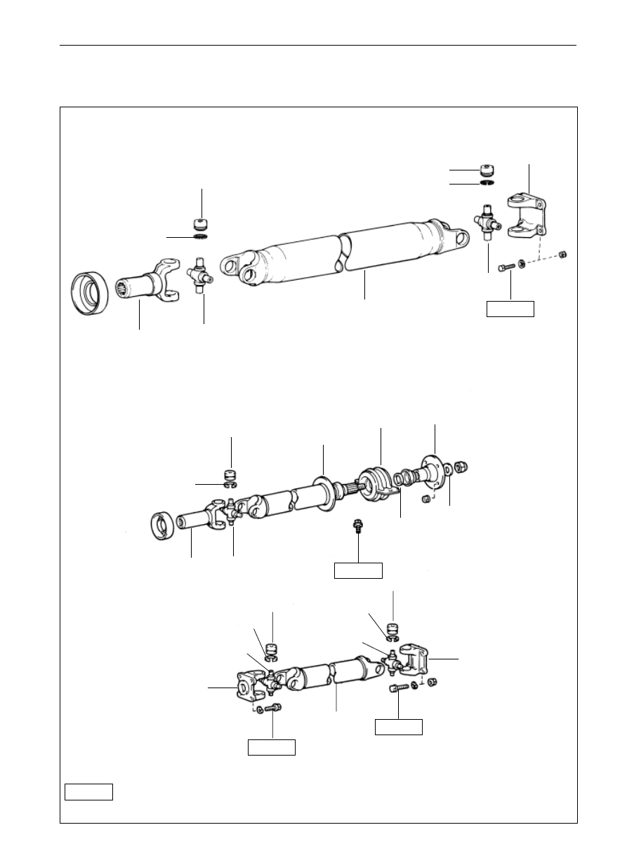
Element Drawing
2WD
two-joint type
snapping ring
bearing of cross shaft
universal joint flange fork
rear axle drive shaft
universal joint foke
cross shaft
three-joint type
snapping ring
bearing of cross shaft
universal
joint foke
cross shaft
front joint of rear
axle drive shaft
center support
bearing
flange
washer
washer
74
5
40
5
universal joint
flange fork
74
5
74
5
universal joint
flange fork
rear section of
rear axle drive
shaft
N*m
: specified torque
Parts that cannot be reused after being used
Drive Shaft
Drive Shaft
-------------------------------------------------------------------------------------------------------------------------------------------------------------
Нет комментариевНе стесняйтесь поделиться с нами вашим ценным мнением.
Текст