Great Wall Socool (2006 year). Service Manual — part 7
PR-4
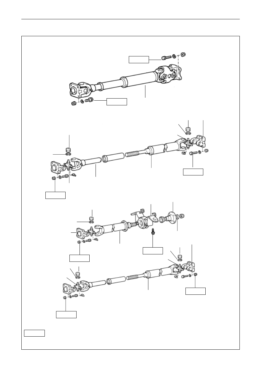
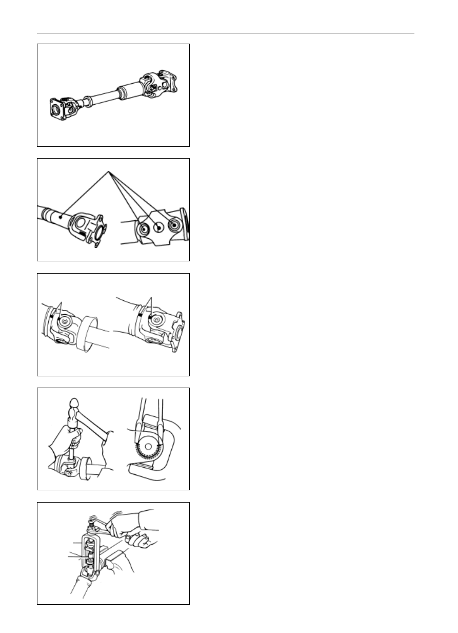
Drive Shaft
Drive Shaft
Element Drawing(continued)
4WD
front axle drive shaft
front axle drive shaft
74
5
74
5
rear axle drive shaft
two-joint type
snapping ring
bearing of cross shaft
74
5
74
5
cross shaft
universal joint yoke
rear axle drive shaft
universal joint flange fork
three-joint type
74
5
40
5
snapping ring
bearing of cross shaft
center support
bearing
flange
front joint of rear
axle drive shaft
washer
universal joint flange fork
74
5
74
5
rear section of
rear axle drive
shaft
universal joint
flange fork
Parts that cannot be reused after being used
N*m
: specified torque
-------------------------------------------------------------------------------------------------------------------------------------------------------------
PR-5
Drive Shaft
Drive Shaft
(4WD)
Rear axle drive shaft
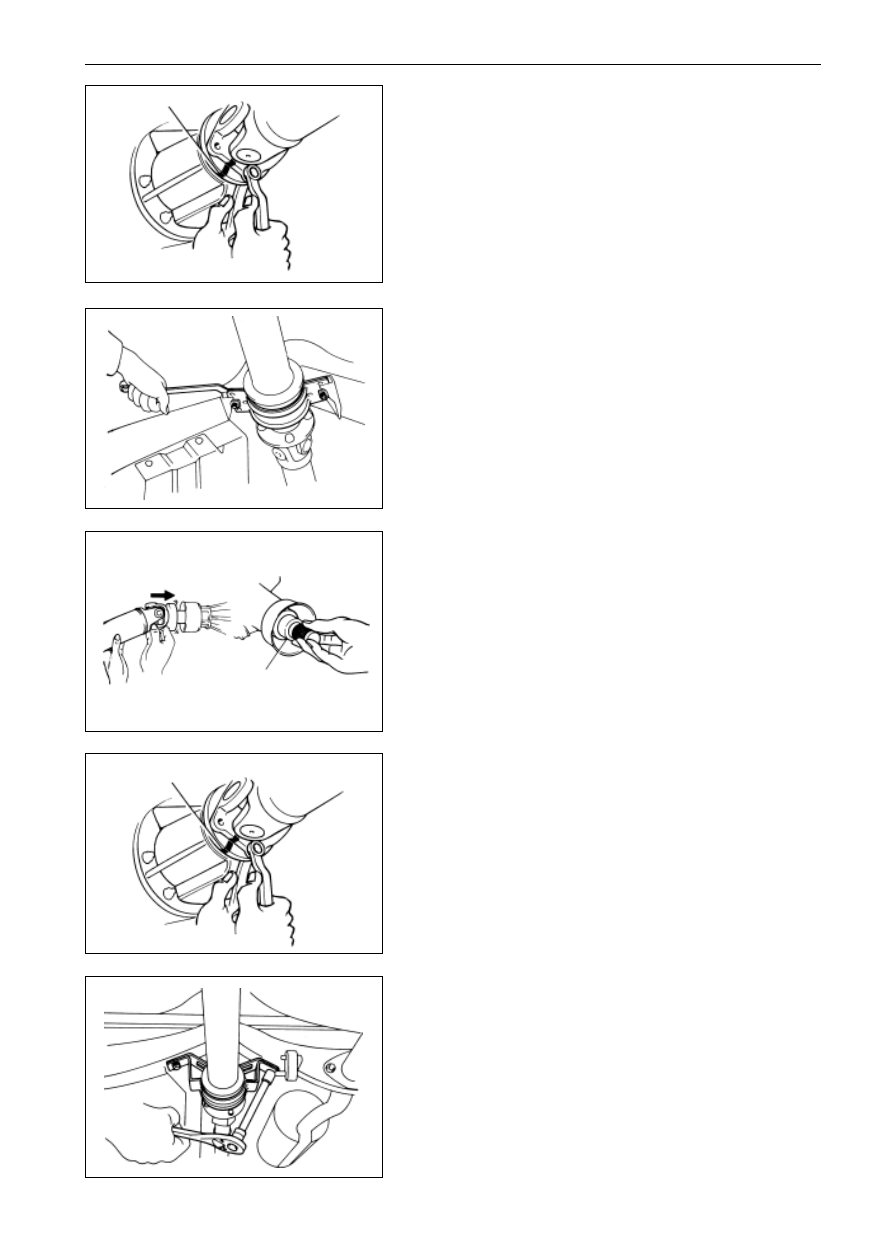
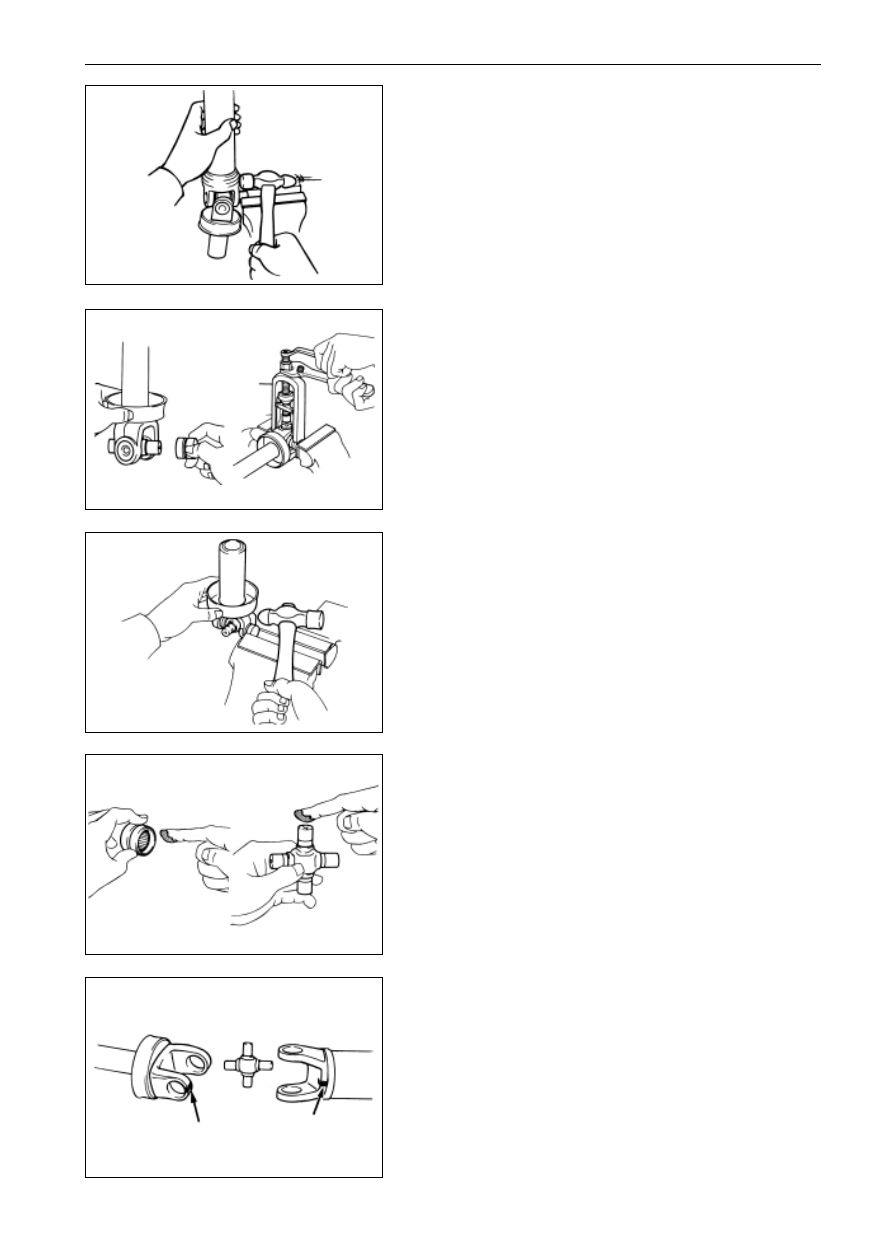
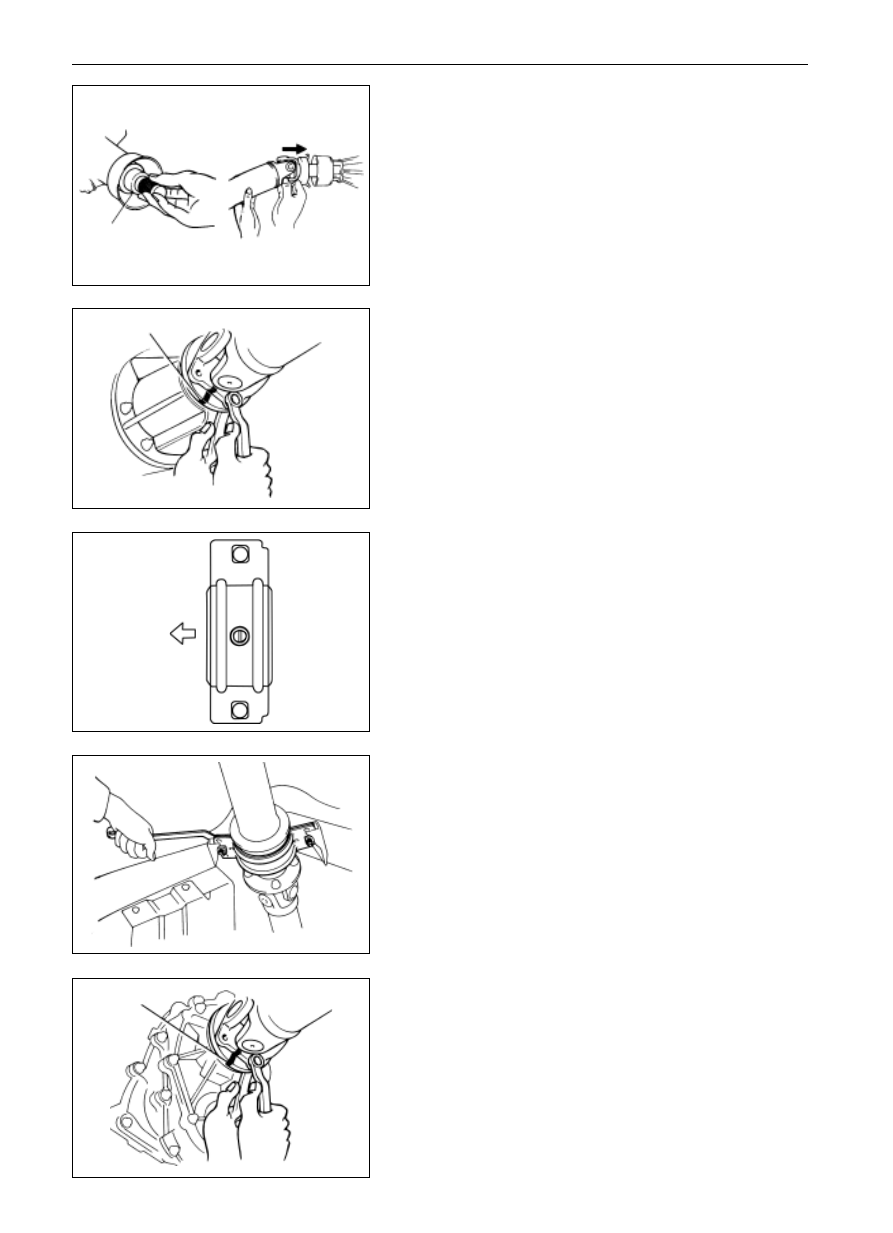
1.
Take apart the universal joint flange fork of rear axle drive
shaft from the differential flange.
(a)
Label the two flanges with assembly marks.
(b)
Take apart the four sets of bolt and nut.
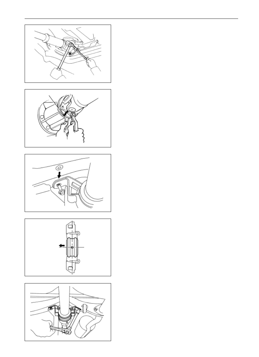
Disassembly of Drive Shaft
(2WD)
1.
Take apart the universal joint flange fork of the drive shaft
from the differential flange.
(a)
Label the two flanges with assembly remarks.
(b)
Take apart the four sets of bolt and nut.
assembly mark
2.
Take apart the center support bearing from the frame
beam (for the three-joint type)
3.
Take apart the drive shaft from the gearbox
(a)
Pull out the universal joint yoke from the gearbox.
(b)
Insert the SST in gearbox for oil leakage prevention.
2.
Take apart the center support bearing from the frame
beam (three-joint type
SST
assembly mark
-------------------------------------------------------------------------------------------------------------------------------------------------------------
PR-6
Drive Shaft
Drive Shaft
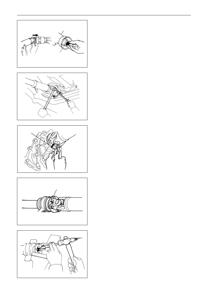
3.
Take apart the drive shaft from the gearbox.
(a)
Pull out the universal joint yoke from the gearbox.
(b)
Insert the SST in gearbox to prevent the oil leakage
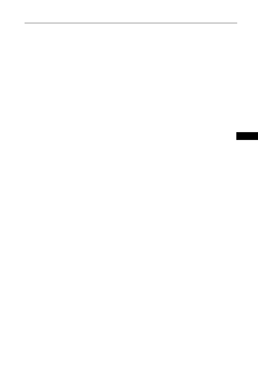
Front axle drive shaft
4.
Tear down the front universal joint flange fork of the front
drive shaft.
(a)
Hang he front end of the front axle drive shaft.
(b)
Label the assembly mark on the flange
(c)
Take apart the four sets of bolt and nut.
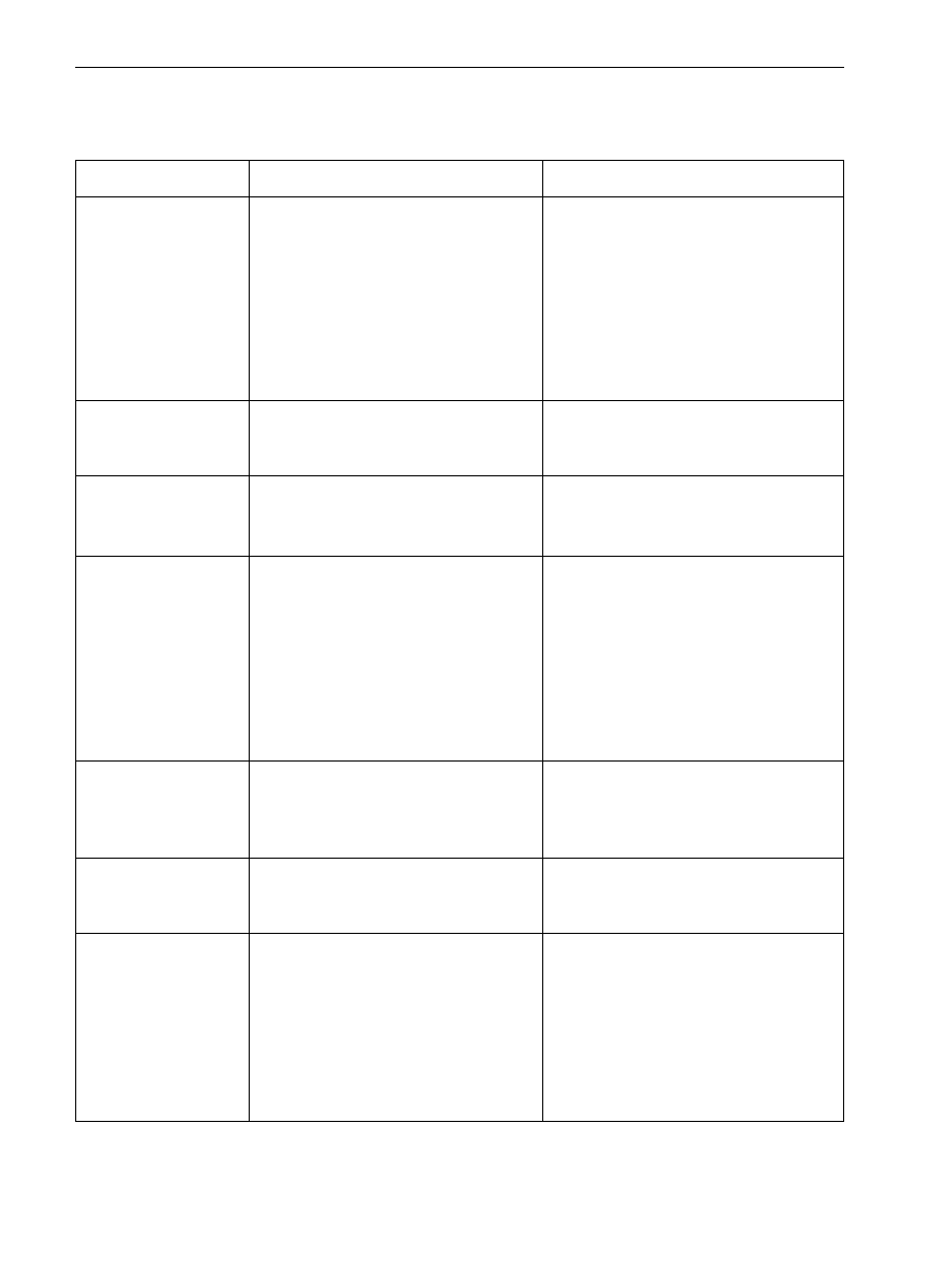
5.
Disconnect the rear universal joint flange fork from the
front axel drive shaft along the transmission path.
(a)
Label the assembly marks on each flange.
(b)
Take apart the four sets of bolt and nut.
Drive shaft disassembly
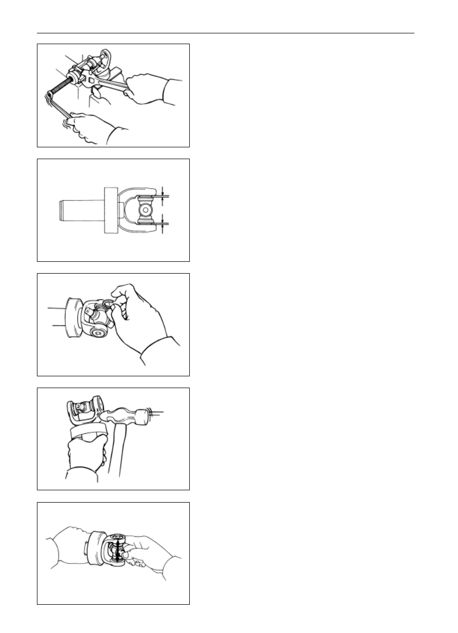
1.
Separation of the rear joint of the rear axle drive shaft
from the front joint of rear axle drive shaft
(a)
Label the assembly marks on each flange.
(b)
Take apart the four sets of bolt and nut.
2.
Take apart the center support bearing from the front joint
of the rear axle drive shaft.
(a)
Loosen the riveted nut by chiseling with a chisel and
hammer.
SST
assembly mark
assembly mark
-------------------------------------------------------------------------------------------------------------------------------------------------------------
PR-7
Drive Shaft
Drive Shaft
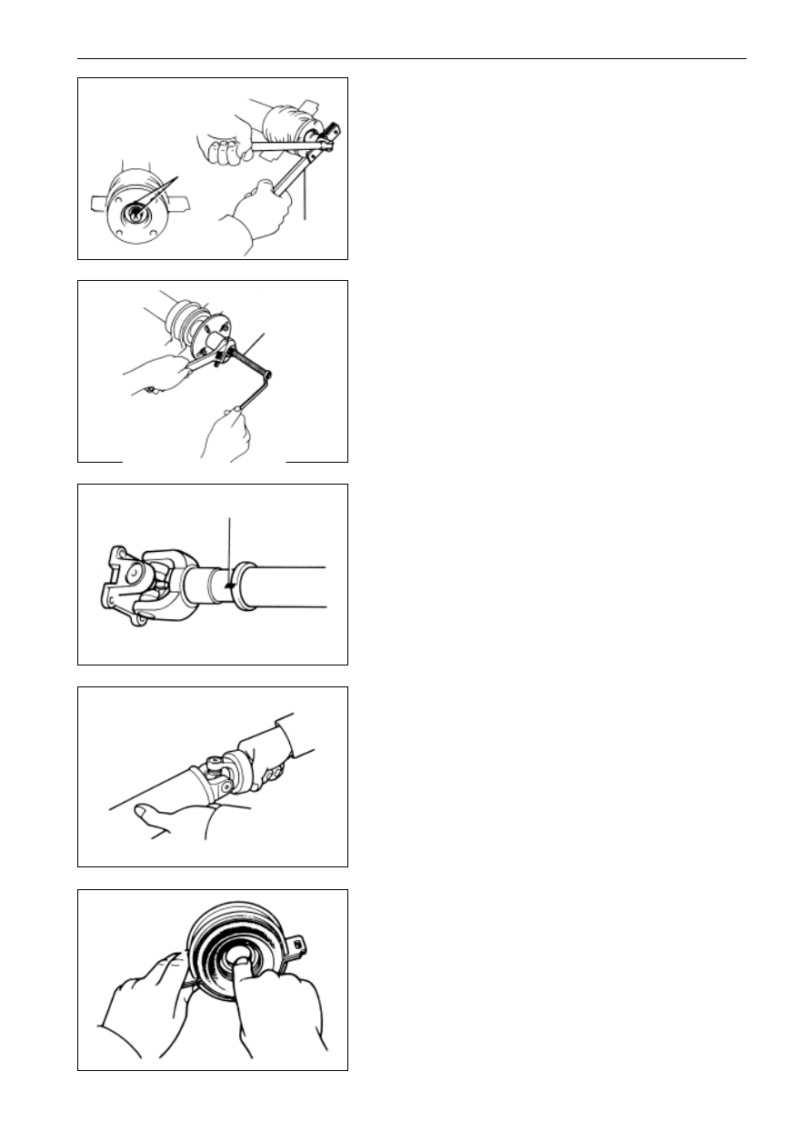
(b)
Lock the flange with SST tools to tear down the nuts.
(c)
Label the assembly marks on flange and shaft.
SST
SST
assembly mark
assembly mark
(d)
Tear down the flange from the front joint of rear axle
drive shaft with SST tools.
3.
Take apart the universal joint yoke from the rear joint of
rear axle drive shaft.
(a)
Label the universal joint yoke and the shaft with assem-
bly marks.
(b)
Pull out the universal joint yoke from the shaft.
Inspection on Drive Shaft Parts
1.
Cross shaft bearing inspection
Check the wear or damage situation of the cross shaft bearing
and change the weary or damaged bearing where necessary.
2.
Check the wear and damage situation of the central
bearing.
Check the bearing to see whether it can run freely.
In case that the bearing is damaged or wearied or cannot run
freely, change it in time.
-------------------------------------------------------------------------------------------------------------------------------------------------------------
PR-8
Drive Shaft
Drive Shaft
3.
Inspection for the front axle drive shaft
(a)
Check the wear or damage situation of the shaft.
(b)
Check the wear or damage situation of the two universal
joints
grease nozzle
rear axle drive shaft
front axle drive shaft
assembly mark
assembly mark
SST
A
4.
Inspection for the drive shaft lubrication
If the drive shaft is not lubricated completely, add the Lithium
base lubricant grease with SST.
Cross bearing change
1.
Label the shaft and universal joint yoke with assembly
marks.
2.
Take apart the snapping ring.
(a)
Tap in the outer bearing race lightly.
(b)
Take apart the four snapping rings in the grooves with
two screwdrivers.
3.
Take apart the cross shaft bearing
(a)
Pull out the bearing from the drive shaft with SST tools.
Remarks: Pull up the part A in the drawing to a enough height
so that it cannot contact the bearing.
-------------------------------------------------------------------------------------------------------------------------------------------------------------
PR-9
Drive Shaft
Drive Shaft
SST
(c)
Mount the two outer bearing races that are taken apart on
the cross shaft.
(d)
Pull out the bearing on the universal joint yoke with SST
tool, and
(b)
Grip the outer bearing race with a vice to tap out the drive
shaft lightly with a hammer.
Remarks: Take apart another bearing with the same approach.
4.
Cross shaft bearing mount
(a)
Coat the lithium base grease on the cross shaft and the
bearing.
Remarks: do not over coat the lubricant.
(b)
Align the assembly marks on the universal yoke and on
the shaft.
(e)
Grip the outer bearing race in the vice and tap lightly out
the universal joint yoke with a hammer.
Remarks: the bearing at the other end may be taken apart with
the same approach.
-------------------------------------------------------------------------------------------------------------------------------------------------------------
PR-10
Drive Shaft
Drive Shaft
5.
Snapping ring mount
(a)
Mount two snapping rings with the same thickness.
Remarks: Do not use the used snapping ring.
(b)
Tap the universal joint yoke lightly with a hammer until
there is no clearance between the outer bearing race and
the snapping ring.
6.
Cross shaft bearing inspection
Check the cross shaft bearing to see whether it can run freely
Remarks: the approach for mounting the cross shaft bearing at
the bearing end is the same.
(c)
Encase the new cross shaft in the universal joint yoke.
(d)
Mount the new bearing on the cross shaft with SST tool,
and
SST
(e)
Adjust the two bearings with SST tool so that the widths
of two snapping ring grooves are equal and maximum.
-------------------------------------------------------------------------------------------------------------------------------------------------------------
PR-11
Drive Shaft
Drive Shaft
Drive shaft assembly
1.
Mount the center support bearing on the front joint of rear
axle drive shaft.
Remarks: The notch of the center support bearing shall face
backward when mounting it.
2.
Mount the flange joint on the front joint of rear axle drive
shaft.
(a)
Coat the spline of front joint of rear axle drive shaft with
lithium base grease.
(b)
Mount flange joint on the shaft and align the assembly marks.
Remarks: if the central flange joint or the front joint of the rear
axle drive shaft is required to change, the front and back
universal joint yokes of the rear axle drive shaft shall face in the
same direction when re-assembling.
(c)
Lock the flange joint with SST and screw up the newly-
changed nut to press the bearing in place.
(d)
Loosen the nuts.
(e)
Tighten the nuts again, and
(f)
Rivet the nuts with hammer and punch.
3.
Drive shaft mount
(a)
Align the assembly marks on flanges, and connect the
two flanges with four sets of bolt and nut.
Remarks: if the central flange or the front joint of the rear axle
drive shaft is required to be changed, the front and back
universal joint yokes of the front joint of rear axle drive shaft
shall face in the same direction when reassembling them.
(b)
Screw up the sets of bolt and nut according to the
specified torque.
Fastening torque: (74
5)Nm
4.
Insert the universal joint yoke in the universal joint yoke
(4WD).
(a)
Coat the lithium base grease on the sliding surfaces of the
drive shaft spline and the universal joint yoke.
(b)
Align the assembly marks on universal joint yoke and
drive shaft.
(c)
Insert the universal joint yoke in drive shaft.
assembly mark
2WD
4WD
forward
assembly mark
SST
assembly mark
-------------------------------------------------------------------------------------------------------------------------------------------------------------
PR-12
Drive Shaft
Drive Shaft
Mount of Drive Shaft
(2WD)
1.
Insert the universal joint yoke in the gearbox.
(a)
Tear down the SST tools.
(b)
Push the universal joint yoke into the gearbox.
2.
Connect the universal joint flange of the rear joint of rear
axle drive shaft and the relative the differential flange.
(a)
Align the assembly marks on the two flanges and connect
the flanges with four sets of bolt and nut.
(b)
Screw up the sets of bolt and nut according to the
specified torque.
Fastening torque
(74 5)Nm
3.
Mount the center support bearing on the frame beam
(three-joint type)
(a) Use two bolts to mount the center support bearing on the
frame beam and tighten them manually.
(b) Check the bearing seat, which shall be vertical with the
drive shaft, and change it where necessary.
(c) Check the central line of the central bearing and ensure
that the central lines of the central bearing and the bear-
ing seat shall be the same when the vehicle is in the non-
loaded stage. And adjust the bearing seat only it is
necessary.
(d) Screw up the mounting bolts according to the specified
torque.
Fastening torque
(40 5)Nm
(4WD)
1.
Connect the universal joint flange fork of the front axle
drive shaft with the flange that matches with the transfer
box.
Align the assembly marks and use four sets of bolt and nut to
connect the flange fork with the flange, screw up the sets of bolt
and nut according to the specified torque.
Fastening torque
(74 5)Nm
forward
SST
assembly mark
assembly mark
-------------------------------------------------------------------------------------------------------------------------------------------------------------
PR-13
Drive Shaft
Drive Shaft
2.
Mount on the front axle drive shaft.
Mount on it and screw up the four bolts according to the
specified torque.
Fastening torque
(74 5)Nm
3.
Connect the universal joint flange fork of the rear axle
drive shaft on the relative differential flange.
(a)
Align the assembly marks on flanges and connect the
flanges with four sets of bolt and nut, and
(b)
Tighten the sets of bolt and nut according to the specified
torque.
Fastening torque
(74 5)Nm
4.
Mount the center support bearing on the frame beam
(three joint type)
(a)
Use two mounting bolts to mount the center support
bearing on the frame beam and screw up them manually.
(b)
Check the bearing seat, which shall be vertical with the
drive shaft, and adjust the bearing seat when necessary.
(c)
Check the central line of the central bearing. The central
line of the central bearing shall be the same with that of
the bearing seat when vehicle is in the non-loaded stage.
(d)
Adjust the bearing seat if necessary, and
(e)
Screw up the mounting bolts according to the specified
torque.
Fastening torque
(40 5)Nm
assembly mark
forward
-------------------------------------------------------------------------------------------------------------------------------------------------------------
SA-1
Suspension System and Automobile Axle
Page
Troubleshooting . . . . . . . . . . . . . . .. SA-2
Alignment of Front Wheel . . . . . . . . . . . SA-3
(Dr/2WD)
Front Wheel Hub and Steering Knuckle . . . . . .. SA-10
Front Wheel Hub . . . . . . . . . . . . . . SA-11
Steering Knuckle . . . . . . . . . . . . . . SA-14
Front Suspension . . . . . . . . . . . . . . SA-16
Ball Stud . . . . . . . . . . . . . . . . .. SA-17
Torsion bar . . . . . . . . . . . . . . . .. SA-19
Lower Arm and Vibration Damper . . . . . . ... SA-21
Upper Arm . . . . . . . . . . . . . . . ... SA-24
Guide Level . . . . . . . . . . . . . . . . SA-26
Lateral Stabilizer . . . . . . . . . . . . . . SA-27
(SF/2WD)
Front Wheel Hub and Steering Knuckle . . . . . .. SA-28
Front Wheel Hub . . . . . . . . . . . . . . SA-29
Steering Knuckle . . . . . . . . . . . . . . SA-32
Front Suspension . . . . . . . . . . . . . . . SA-36
Ball Stud . . . . . . . . . . . . . . . . ... SA-37
Torsion bar . . . . . . . . . . . . . . . ... SA-38
Lower Arm and Vibration Damper . . . . . . . SA-39
Upper Arm . . . . . . . . . . . . . . . . SA-42
Guide Level . . . . . . . . . . . . . . . .. SA-43
Lateral Stabilizer . . . . . . . . . . . . . ... SA-43
(SF/4WD)
Front Wheel Hub and Steering Knuckle . . . . . ... SA-44
Front Wheel Hub . . . . . . . . . . . . . .. SA-45
Steering Knuckle . . . . . . . . . . . . . . SA-49
Constant Speed Drive Shaft . . . . . . . . . . SA-54
Front Speed Reducer . . . . . . . . . . . . .. SA-57
Change of Oil Seal of Driving Bevel Gear Of
Front Speed Reducer . . . . . . . . . . . . SA-57
Dismantle of Front Speed Reducer . . . . . . . SA-61
Change of Axle Shaft Oil Seal . . . . . . . . . SA-63
Disassembly and Assembly of Front Speed Reducer . SA-65
Assembly of Front Speed Reducer . . . . . . . SA-74
(Back)
Rear Axle Shaft . . . . . . . . . . . . . . ... SA-79
Rear Speed Reducer . . . . . . . . . . . . .. SA-83
On-vehicle Change of Oil Seal of Main Teeth . . . SA-84
Dismantle of Rear Speed Reducer . . . . . . .. SA-85
Disassembly of Rear Speed Reducer . . . . . . SA-85
Assembly of Rear Speed Reducer . . . . . . .. SA-89
Mount of Rear Speed Reducer and
Differential Assembly . . . . . . . . . . . .. SA-94
Rear Differential . . . . . . . . . . . . . . .. SA-95
Rear Suspension . . . . . . . . . . . . . . . SA-97
SA
-------------------------------------------------------------------------------------------------------------------------------------------------------------
SA-2
Troubleshooting
Suspension System and Automobile Axle
Troubleshooting
Change the tire or inflate to the proper pressure
Balance the wheels
Change vibration damper
Check Alignment of Front Wheel
Change or adjust the wheel bearing
Check ball joint) or liner
Tighten or change steering linkage
Adjust or repair the steering device
Discharge the oil and change with new one
Check the wandering clearance
Check the gears
Change the bearing
Change the bearing
Tighten or change the bearing
Trouble
Causes
Inspection items
Body wandering/body
dragging
Tire wear or improper air inflation
Incorrect alignment of front wheel
Over-tightened wheel bearing
Part looseness or damage of front/rear sus-
pension
Wear or looseness of steering rod system
Poor connection or damage of steering de-
vice
Inflate the tire to the proper pressure or change
the tire.
Check the situation of alignment of front wheel
Adjust the wheel bearing
Tighten or change the suspension element
Tighten or change the steering rod system
Adjust or repair the steering device
Body sink
Overloaded vehicle
Wear of vibration damper
Poor spring performance
Check the loading mass
Change vibration damper
Change spring
Left-right vibration/up-
down bouncing
Improper air inflation
Bending or damaged lateral stabilizer
Vibration damper wear
Inflate the tire to suitable pressure
Change stabilizer
Change vibration damper
Front wheel vibration
Tire wear or improper air inflation
Imbalance of wheels
Vibration damper wear)
Improper Alignment of Front Wheel
Wheel bearing wear or improper adjustment
Ball joint or liner wear
Steering linkage looseness or wear
Poor adjustment or damage of steering mecha-
nism
Abnormal tire wear
Improper air inflation
Vibration damper wear
Poor Alignment of Front Wheel
Suspension system wear
Inflate the tire to the proper pressure
Change vibration damper
Check the Alignment of Front Wheel
Change suspension element
Speed reducer leakage
Over-high oil level or improper oil quality
Oil seal wear or damage
Flange looseness or damage
Discharge the oil for change
Change oil seal
Tighten or change the flange
Noise inside the
axleNoise inside the axle
Over-low oil level or inferior oil quality
Over-large wandering clearance between
driving bevel gear and driven bevel gear
Wear and disintegration of driving bevel
gear and driven bevel gear
Bearing wear of driving bevel gear
Bearing wear of rear axle shaft
Bearing looseness or wear of speed reducer
-------------------------------------------------------------------------------------------------------------------------------------------------------------
SA-3
Suspension System and Automobile Axle
Alignment of Front Wheel (Dr SL SK SY SJ)
Alignment of Front Wheel
(Dr SL SK SY SJ)
1.
Inspection should be conducted for the following items to
remove the trouble
(a)
Check the tire abrasion and air inflation situation
Tire inflation pressure:
Front (220
0)kPa
Back (240
0)kPa
(b)
Check the front wheel bearing to see whether it is loose.
(c)
Check the front suspension to see whether it is loose.
(d)
Check the steering driving device to see whether it is
loose, and
(e)
Check the front vibration damper work to see whether it
is loose.
2.
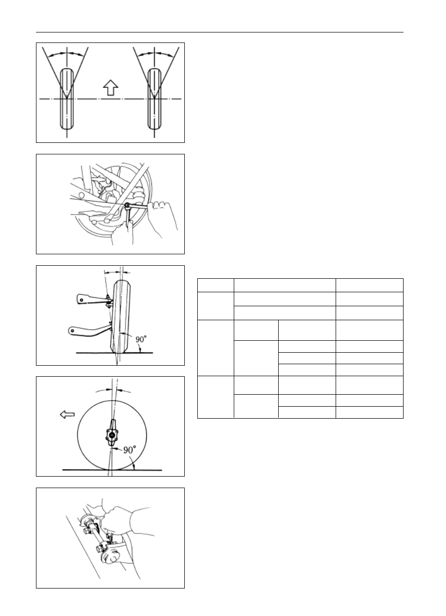
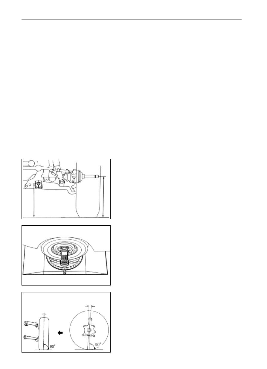
Measure the ground clearance of the chassis.
Chassis ground clearance:
Dr
295
0
+5
mm
SL SK
(255 2)mm
SY
(310 2)mm
SJ
(295 1)mm
If the chassis ground clearance of the vehicle is sub-standard,
push down the body or raise it for a trial adjustment, if fails,
check the spring or suspension element to see whether they are
normal.
Remarks: adjust the chassis ground clearance to a specified
value before checking the Alignment of Front Wheel
parameters.
3.
Mount on the four-wheel locating device.
The mount should be conducted according to the manufacturerís
instructions.
-------------------------------------------------------------------------------------------------------------------------------------------------------------
SA-4
Suspension System and Automobile Axle
Alignment of Front Wheel (Dr SL SK SY SJ)
5.
Adjustment for inner tilt angle of kingpin, outer tilt angle
of front wheel and back tilt angle of kingpin
Item
Inner tilt
angle of
kingpin
Outer tilt
angle of
front
wheel
Applicable vehicle type
Dr SL SK SY
SJ
M e c h a n i c
steering
Dr SL SK SY
Power
steering
Dr
SL SK SY
SJ
Back tilt
angle of
kingpin
M e c h a n i c
steering
Dr SL SK SY
Power steer-
ing
Dr SL SK SY
SJ
9
30 45
14
52
0
30 20
0
10 10
0
20 10
0
30 15
2
45 15
3
15
Location parameter
4.
Adjust the wheel angle
Take apart the limit bolts of the steering knuckle to check the
steering angle A of inner wheel.
Inner wheel steering angle
Dr SL SK SY
( 3640)
SJ
( 3234)
Remark: The wheel should not contact the body or brake hose
when the steering wheel reaches the limit position.
In case the steering angle of inner wheel doesnít conform to the
standard value, adjust the wheel angle through adjusting the
limit bolts of the steering knuckle.
Fastening torque
(90 0)Nm(SJ)
If the wheel angle fails to be adjusted within the standard value,
change the weary or damaged parts of steering system.
If the tilt angle fails to fall within the specified values, make an
adjustment through adding or reducing the gaskets on the
location of upper arm.
Gasket thickness: 3.0, 2.0 and 1.0mm
Once the gasket thickness increases by 1mm, the outer tilt
angle of wheel will change by 7', while the back tilt angle of
kingpin will change 20'.
After the wheel outer tilt angle and the back tilt angle of kingpin
are adjusted, if the inner tilt angle of kingpin still fails to the
specified value, check the steering knuckle or front wheel to
see whether they are bending or loose.
1
50
-20
adjusting bolt
outer tilt
angle of
front wheel
inner tilt angle of kingpin
back tilt angle of
kingpin
front
A
B
A
B
HPM
-------------------------------------------------------------------------------------------------------------------------------------------------------------
SA-5
7.
Check the sliding measuring situation.
Check the sliding situation with the sliding measuring tester.
Sliding measuring value:
.5m/km
push forward the vehicle;
forward
A=B
B
A
6.
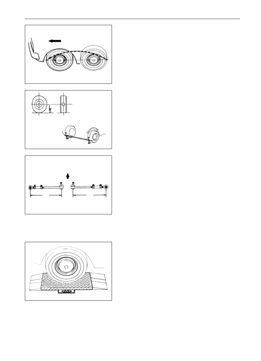
Wheel toe-in adjustment
(a)
Verify that each wheel has been located forward in a line.
(b)
Mark the tire center at the bearing height on the tread of
left and right tire, and measure the distance between the
marks on left and right treads.
(c)
Push forward the vehicle until the mark on the back tread
of tire moves to the front.
Remark: the toe-in measurement should be conducted from the
same spot at the same height.
(d)
Measure the distance between the two marks on the front
of two treads.
Toe-in value: (0-2)mm
(e)
Loosen the clamping bolts of connecting pipe.
(f)
Adjust the toe-in angle through the approach according to
which rotate the left and right drag rod tube by a same
angle.
Remark: check the lengths of the two drag rods to see whether
the two rods are same in length.
Length error of the left and right drag rod should not
be larger than 2.0mm.
(g)
Tighten the clamping bolts.
Fastening torque
(20 ) Nm
(h)
Locate the split pin well.
Suspension System and Automobile Axle
Alignment of Front Wheel (Dr SL SK SY SJ)
-------------------------------------------------------------------------------------------------------------------------------------------------------------
SA-6
Suspension System and Automobile Axle
Alignment of Front Wheel Alignment of Front Wheel (SF)
Alignment of Front Wheel
(SF)
1.
The following items should be checked to remove the
troubles.
(a)
Check the tire abrasion and the air inflation to see it is
suitable or not.
Tire inflation pressure: (250
0)kPa
(b)
Check the front wheel bearing to see whether it is loose.
(c)
Check the front suspension to see whether it is loose.
(d)
Check the steering driving device to see whether it is
loose, and
(e)
Check the front vibration through elastic force test to see
whether it is normal in performance.
2.
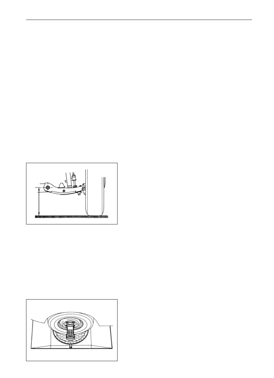
Height adjustment of vehicle
Adjust the vehicle height to the standard value so as to make
the Alignment of Front Wheel inspection.
A-B-58 5mm
A: The height of steering knuckle shaft center.
B: The center height of the adjusting cam bolt at front end
The standard value for the unloaded height is: the
difference of the center height of drive shaft climax and
the front adjusting cam bolt is 58.5mm.
3.
Mount on the four wheel locating device
This approach should be conducted according to the detailed
instruction of the equipment manufacturer.
4.
Adjust the outer tilt angle of front wheel and the back tilt
angle of kingpin
The outer tilt angle of front wheel: 0
5' 0'
The back tilt angle of kingpin: 2
0' 0'
Outer inclination of front wheel:
B
A
the outer tilt angle of
front wheel
the back tilt angle
of kingpin
front
-------------------------------------------------------------------------------------------------------------------------------------------------------------
Нет комментариевНе стесняйтесь поделиться с нами вашим ценным мнением.
Текст