Lexus LC500C (2022 year). Manual in english — page 14
233
5-3. Using the air conditioning system
5
Interio
r fe
atures
Prevent ice from building up on the
windshield and wiper blades
(Windshield wiper de-icer) (if
equipped)
Removing pollen from the air
(Micro dust and pollen filter)
■
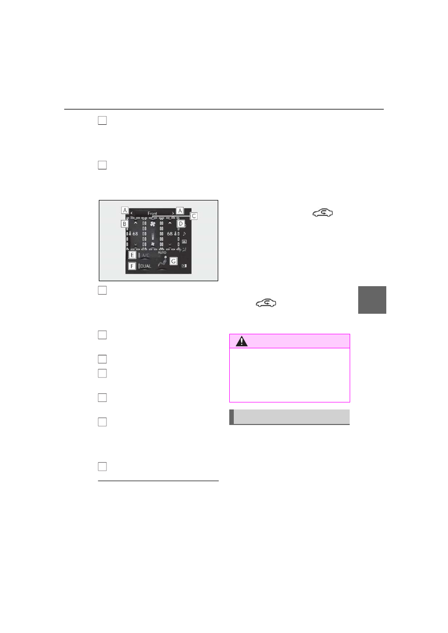
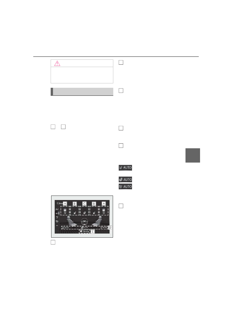
Side display
Display the heated steering wheel
(if equipped)/seat heaters/seat
ventilators control screen
(
Adjust the left-hand side tempera-
ture setting
Adjust the fan speed setting
Adjust the right-hand side tem-
perature setting
Set cooling and dehumidification
function on/off
Adjust the temperature for the
driver’s and front passenger’s seats
separately (“DUAL” mode)
(
Select the air flow mode
■
Windshield wiper de-icer (if equipped)
This feature is used to prevent ice from
building up on the windshield and wiper
blades.
The windshield de-icer will automatically
turn off after approximately 15 minutes.
■
Eco air conditioning mode
When Eco drive mode is selected using the
driving mode select switch, eco air condi-
tioning mode turns on.
When a drive mode other than Eco drive
mode is selected, eco air conditioning
mode may turn off.
■
Micro dust and pollen filter
Outside air mode switches to
(recirculated air) mode. Pollen is removed
from the air and the air flows to the upper
part of the body.
Usually the system will automatically turn
off after approximately 1 to 3 minutes.
In order to prevent the windshield from fog-
ging up when the outside air is cold, the
dehumidification function may operate or
the outside/recirculated air mode may not
switch to
(recirculated air) mode.
Pollen is filtered even if the micro dust and
pollen filter is turned off.
1
Press the automatic mode switch
or select “AUTO” on the sub func-
tion menu. (
2
Press the outside/recirculated air
mode switch to switch to automatic
air intake mode.
The air conditioning system automatically
switches between outside air and recircu-
lated air modes.
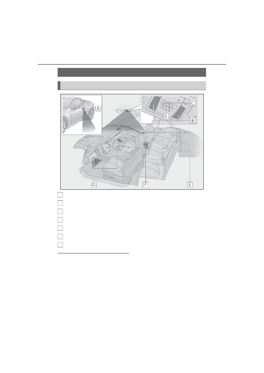
E
F
A
B
C
D
E
F
G
WARNING
■
To prevent burns (vehicles with wind-
shield wiper de-icer)
Do not touch the glass at lower part of
the windshield or to the side of the front
pillars when the windshield wiper de-icer
is on.
Using automatic mode
234
5-3. Using the air conditioning system
3
Adjust the temperature setting.
4
To stop the operation, press the off
switch or select “Off” on the sub
function menu. (
If the fan speed setting or air flow
modes are operated, the automatic
mode indicator goes off. However,
automatic mode for functions other
than that operated is maintained.
■
Using automatic mode
●
Fan speed is adjusted automatically
according to the temperature setting and
the ambient conditions.
Therefore, the fan may stop for a while until
warm or cool air is ready to flow immedi-
ately after the automatic mode switch is
pressed or “AUTO” is selected.
●
Cool air may blow around the upper
body even when the heater is on due to
sunlight.
●
When the soft top roof is opened, the fan
speed and air outlets may be automati-
cally changed according to the sunlight
or vehicle speed.
■
Windshield fog detection function
When automatic mode is set, the humidity
sensor detects fog on the windshield and
controls the air conditioning system to pre-
vent fog.
■
Automatic mode for air intake control
In automatic mode, the system detects
exhaust gas and other pollutants and auto-
matically switches between outside air and
recirculated air modes.
When the dehumidification function is off,
and the fan is operating, turning automatic
mode on will activate the dehumidification
function.
To turn on the “DUAL” mode, perform
any of the following procedures:
Select “DUAL” on the sub function
menu. (
Select “DUAL” on the option con-
trol screen.
Adjust the passenger’s side tem-
perature setting.
The indicator on the main control screen
comes on when the “DUAL” mode is on.
■
Location of air outlets
The air outlets and air volume changes
NOTICE
■
Humidity sensor
In order to detect fog on the windshield,
a sensor which monitors the temperature
of the windshield, the surround humidity,
etc. is installed.
Follow these points to avoid damaging
the sensor:
●
Do not disassemble the sensor
●
Do not spray the glass cleaner on the
sensor or subject it to strong impacts
●
Do not stick anything on the sensor
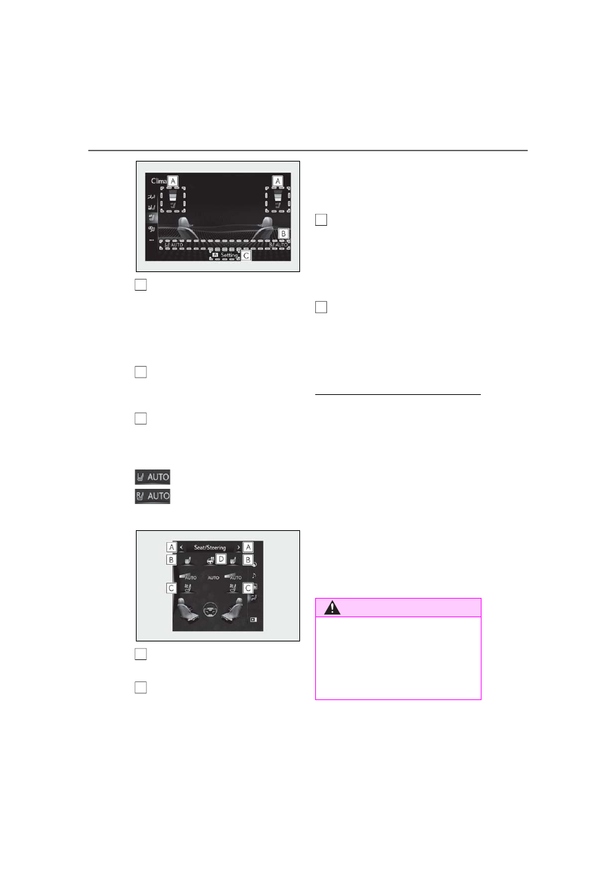
Adjusting the temperature for
driver and passenger seats sepa-
rately (“DUAL” mode)
Air outlet layout and operations
235
5-3. Using the air conditioning system
5
Interio
r fe
atures
according to the selected air flow
mode.
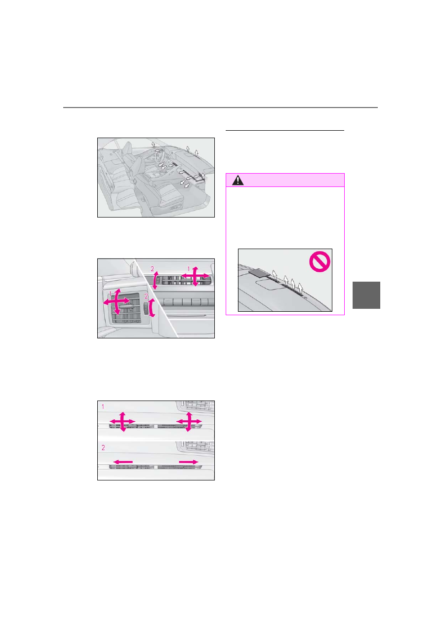
■
Adjusting the air flow direction and
opening/closing the air outlets
Center/side
1
Direct air flow to the left or right, up
or down
2
Turn the knob to open or close the
vent
Above the glove box
1
Direct air flow to the left or right, up
or down
2
Move the knob to the most outside
position to close the vent
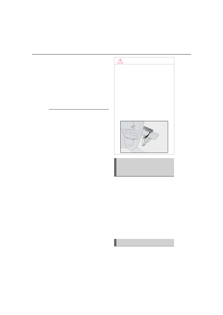
■
If an object falls into the air outlet above
the glove box
Remove the panel inside the glove box to
take out the object. (
WARNING
■
To prevent the windshield defogger
from operating improperly
Do not place anything on the instrument
panel which may cover the air outlets.
Otherwise, air flow may be obstructed,
preventing the windshield defoggers
from defogging.
236
5-3. Using the air conditioning system
*
: If equipped
Heated steering wheel
*
/seat
heaters/seat ventila-
tors/neck heaters
*
Heated steering wheel
Warms up the grip of the steering wheel
Seat heaters
Warm up the seat upholstery
Seat ventilators
Maintain good air flow on the seat
upholstery by sucking air into the seats
Press the “MENU” button on the
Remote Touch and select “Cli-
mate” to display the air condition-
ing control screen. Then, select
on the sub menu (
P.231) to dis-
play the heated steering
wheel/seat heaters/seat ventila-
tors control screen.
Neck heaters
Warm up the head restraints near
the neck by blowing the warm air
from the air outlet on the head
restraints
Press the “MENU” button on the
Remote Touch and select “Cli-
mate” to display the air condition-
ing control screen. Then, select
on the sub menu (
P.231) to dis-
play the neck heaters control
screen.
WARNING
■
To prevent minor burn injuries
Care should be taken if anyone in the fol-
lowing categories comes in contact with
the steering wheel, seats or neck heaters
when the heater is on:
●
Babies, small children, the elderly, the
sick and the physically challenged
●
Persons with sensitive skin
●
Persons who are fatigued
●
Persons who have taken alcohol or
drugs that induce sleep (sleeping
drugs, cold remedies, etc.)
■
To prevent burns and fire
Do not put fingers or foreign matters into
the air outlets or intake vents. Doing so
may cause burns or fire.
NOTICE
■
To prevent damage to the seat heat-
ers and seat ventilators
Do not put heavy objects that have an
uneven surface on the seat and do not
stick sharp objects (needles, nails, etc.)
into the seat.
■
To prevent damage to the neck heat-
ers
Do not block the air outlets or intake
vents of the neck heaters. If the air outlets
or intake vents become blocked, heat is
accumulated and the neck heaters may
be damaged.
237
5-3. Using the air conditioning system
5
Interio
r fe
atures
■
Main display
Using the touchpad of the Remote
Touch, select the button on the screen.
Except the neck heaters
to
can be adjusted by perform-
ing the following operations.
Flick operation: Move the pointer to
the desired item and flick the touchpad
up or down.
The item can be adjusted by one level.
Trace operation: After selecting the
desired item, trace the pad surface.
The item can be adjusted by the amount
that you trace.
Trace operation cannot be used while driv-
ing.
Adjust the seat ventilator fan speed
level
The seat ventilator can be adjusted in 3
levels.
When the seat ventilator is operated, the
fan speed level is displayed on the screen.
Adjust the seat heater temperature
level
The seat heater can be adjusted in 3 levels.
When the seat heater is operated, the tem-
perature level is displayed on the screen.
Adjust the heated steering wheel
temperature level
The heated steering wheel can be adjusted
in 2 levels.
When the heated steering wheel is oper-
ated, the temperature level is displayed on
the screen.
Automatic mode on/off indicators
When the automatic mode is on, the indi-
cator illuminates on the screen.
Sub function menu
When the sub function button on the
Remote Touch is pressed, the following
functions can be set to automatic mode.
: Left-hand side seat heater/seat
ventilator
: Heated steering wheel
: Right-hand side seat heater/seat
ventilator
Neck heaters
can be adjusted by performing the
following operations.
Flick operation: Move the pointer to
the desired item and flick the touchpad
up or down.
The item can be adjusted by one level.
Trace operation: After selecting the
desired item, trace the pad surface.
The item can be adjusted by the amount
that you trace.
Trace operation cannot be used while driv-
ing.
NOTICE
■
To prevent battery discharge
Do not use the functions when the
engine is off.
Control screen
A
C
A
B
C
D
E
A
238
5-3. Using the air conditioning system
Adjust the neck heater fan speed
level
The neck heater can be adjusted in 3 lev-
els.
When the neck heater is operated, the fan
speed level is displayed on the screen.
Automatic mode on/off indicators
When the automatic mode is on, the indi-
cator illuminates on the screen.
Sub function menu
When the sub function button on the
Remote Touch is pressed, the following
functions can be set to automatic mode.
: Left-hand side neck heater
: Right-hand side neck heater
■
Side display
Display the air conditioning control
screen (
Adjust the seat heater temperature
level
Each time the switch is selected, the tem-
perature level and level indicator (orange)
change as follows:
AUTO
Hi
Mid
Lo
Off
Adjust the seat ventilator fan speed
level
Each time the switch is selected, the fan
speed level and level indicator (blue)
change as follows:
AUTO
Hi
Mid
Lo
Off
Adjust the heated steering wheel
temperature level
Each time the switch is selected, the tem-
perature level and level indicator change
as follows:
AUTO
Hi
Lo
Off
■
The heated steering wheel, seat heaters
and seat ventilators wheel can be used
when
The engine switch is in ON.
■
Air conditioning system-linked control
mode
When the seat ventilator fan speed level is
Hi, the seat ventilator fan speed may
become higher according to the fan speed
of the air conditioning system.
■
Customization
Steering wheel heating preference in auto-
matic mode and the automatic mode set-
tings for the seat heaters and ventilators can
be changed. (Customizable features:
A
B
C
A
B
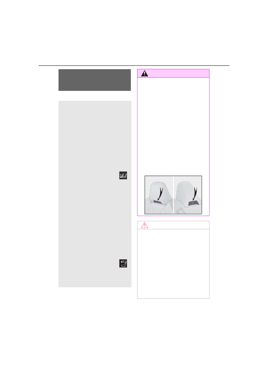
WARNING
■
To prevent overheating and minor
burn injuries
Observe the following precautions when
using the seat heaters.
●
Do not cover the seat with a blanket or
cushion when using the seat heater.
C
D
239
5-3. Using the air conditioning system
5
Interio
r fe
atures
*
: : If equipped
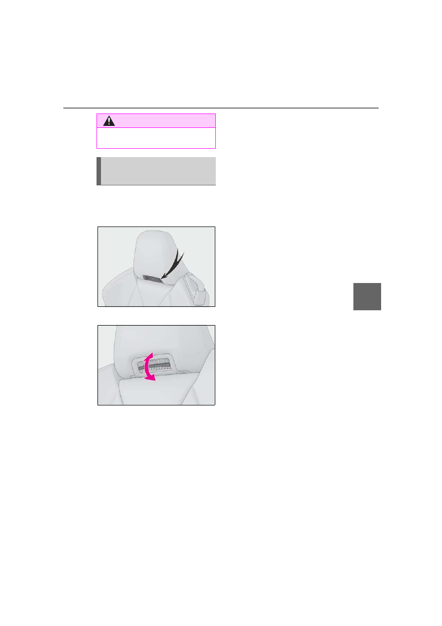
■
Location of the neck heater air out-
let
■
Adjusting the air flow direction
WARNING
●
Do not use seat heater more than nec-
essary.
Location and operation of the
neck heaters
*
air outlet
240
5-4. Using the interior lights
5-4.Using the interior lights
Outside door handle lights
Personal lights (
Seat lights
Shift lever light
Door trim ornament lights
Door courtesy lights
Footwell lights
■
Personal lights automatic on/off
●
Illuminated entry system: The lights auto-
matically turn on/off according to engine
switch mode, the presence of the elec-
tronic key, whether the doors are
locked/unlocked, and whether the doors
are opened/closed.
●
If the personal lights remain on when the
engine switch is turned off, the lights will
go off automatically after 20 minutes.
■
When personal lights do not respond as
normal
●
When water, dirt, etc., have adhered to
the lens surface
●
When operated with a wet hand
●
When wearing gloves, etc.
■
The interior lights will turn on automati-
cally when
If any of the SRS airbags deploy (inflate) or
in the event of a strong rear impact, the
Interior lights list
Location of the interior lights
A
B
C
D
E
F
G
241
5-4. Using the interior lights
5
Interio
r fe
atures
interior lights will turn on automatically. The
interior lights will turn off automatically after
approximately 20 minutes. The interior
lights can be turned off manually. However,
in order to help prevent further collisions, it
is recommended that they be left on until
safety can be ensured. (The interior lights
may not turn on automatically depending
on the force of the impact and conditions of
the collision.)
■
Customization
Setting (e.g. the time elapsed before lights
turn off) can be changed.
(Customizable features:
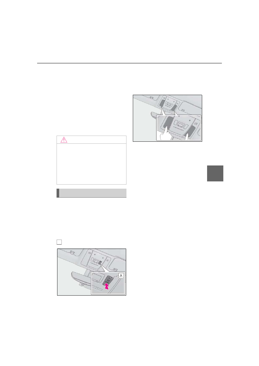
■
Turning the door position on
Press the door-linked personal light
switch
The lights are turned on and off according
to whether the doors are opened/closed.
When the door position is on, the indicator
illuminates.
■
Turning the lights on/off
Touch the light
When a door is opened while the door
position is on, the lights turn on.
NOTICE
■
Removing light lenses
Never remove the lens for the personal
lights. Otherwise, the lights will be dam-
aged.
■
To prevent battery discharge
Do not leave the lights on longer than
necessary when the engine is off.
Operating the personal lights
A
242
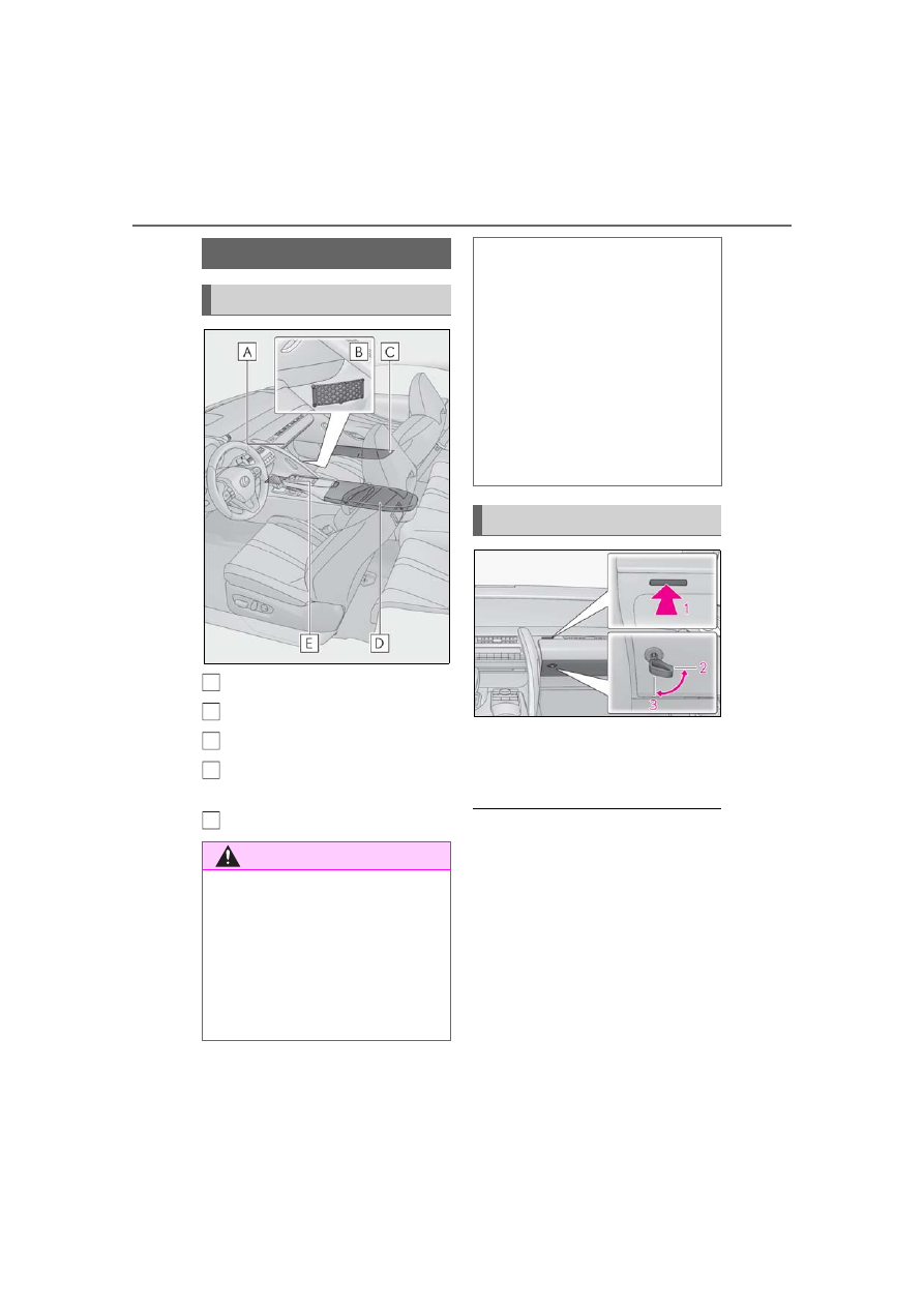
5-5. Using the storage features
5-5.Using the storage features
Glove box (
Auxiliary net
Door pockets
Console box/auxiliary box
(
Cup holder (
1
Open (press the glove box opener)
2
Unlock with the mechanical key
3
Lock with the mechanical key
■
Glove box light
The glove box light turns on when the tail
lights are on.
■
Trunk opener main switch
■
If the battery is discharged
The glove box cannot be opened as usual.
Refer to P.328 to open the glove box.
List of storage features
Location of the storage features
WARNING
■
Items that should not be left in the
vehicle
Do not leave glasses, lighters or spray
cans in the storage spaces, as this may
cause the following when cabin tempera-
ture becomes high:
●
Glasses may be deformed by heat or
cracked if they come into contact with
other stored items.
A
B
C
D
E
●
Lighters or spray cans may explode. If
they come into contact with other
stored items, the lighter may catch fire
or the spray can may release gas,
causing a fire hazard.
■
When storage compartments are not
in use
When driving or when the storage com-
partments are not in use, keep the lids
closed.
In the event of sudden braking or sudden
swerving, an accident may occur due to
an occupant being struck by an open lid
or the items stored inside.
Glove box
243
5-5. Using the storage features
5
Interio
r fe
atures
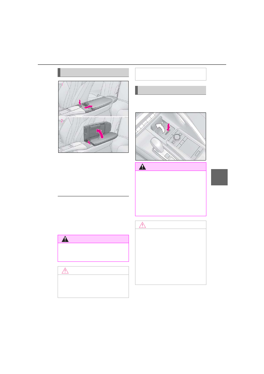
1
Using with half-open: Slide the
armrest as far back while pressing
the button.
Press the button to close.
2
Using with fully open: Lift the arm-
rest while pulling the knob.
■
Console box light
The console box light turns on when the tail
lights are on.
■
Using the auxiliary box
Do not place cups, beverage cans, etc. in
the auxiliary box.
To open, press down and release the
cup holder lid.
Console box/auxiliary box
WARNING
■
When closing the console box
Take care to prevent your fingers etc.
from being caught.
NOTICE
■
To prevent damage to the console
box
●
Do not pull the knob while sliding the
armrest.
●
Do not apply excessive force to the
armrest.
Cup holder
WARNING
■
Items unsuitable for the cup holder
Do not place anything other than a cup
or beverage can in the cup holder. Even
when the lid is closed, items must not be
stored in the cup holder.
Other items may be thrown out of the
holder in the event of an accident or sud-
den braking, causing injury. If possible,
cover hot drinks to prevent burns.
NOTICE
■
To prevent damage to the cup holder
and air conditioning control switches
●
Do not apply excessive force to the
cup holder.
●
Take care when placing a tall bottle in
the cup holder. When the bottle is
taken out or the brakes are suddenly
applied, the bottle may hit the air con-
ditioning control switches, causing
damage to the switches or parts of the
air conditioning system.
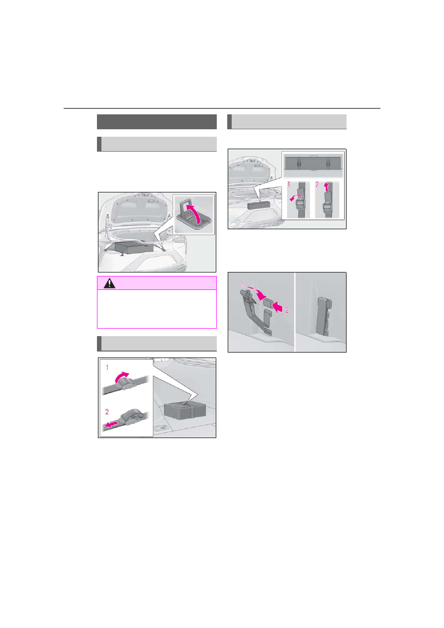
244
5-5. Using the storage features
Raise the hooks when needed.
The cargo hooks are provided for securing
loose items.
1
Loosen the belt
2
Tighten the belt
■
Loosening/tightening the belt
1
Loosen the belt
2
Tighten the belt
■
Stowing the belt
1
Fold the belt
2
Secure the belt with the clip
To prevent damage to the warning reflec-
tor storage belt when it is not in use, stow
the belt.
Trunk features
Cargo hooks
WARNING
■
When the cargo hooks are not in use
To avoid injury, always return the cargo
hooks to their stowed positions when not
in use.
First-aid kit storage belt
Warning reflector storage belt
245
5-6. Using the other interior features
5
Interio
r fe
atures
5-6.Using the other interior features
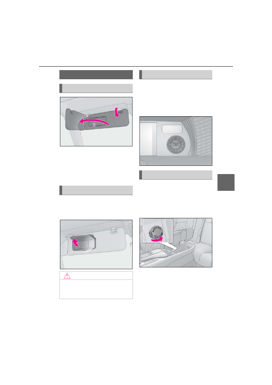
1
To set the visor in the forward posi-
tion, flip it down.
2
To set the visor in the side position,
flip down, unhook, and swing it to
the side.
Open the cover.
The light turns on when the cover is
opened.
The GPS clock’s time is automatically
adjusted by utilizing GPS time infor-
mation.
For details, refer to the “NAVIGATION
SYSTEM OWNER’S MANUAL”.
Please use as a power supply for elec-
tronic goods that use less than 12
VDC/10 A (power consumption of
120 W).
Open the lid.
■
The power outlet can be used when
The engine switch is in ACC or ON.
■
When turning the engine switch off
Disconnect electrical devices with charging
functions, such as mobile battery packs.
If such devices are left connected, the
engine switch may not be turned off nor-
mally.
Other interior features
Sun visors
Vanity mirrors
NOTICE
■
To prevent battery discharge
Do not leave the lights on longer than
necessary when the engine is off.
Clock
Power outlet
246
5-6. Using the other interior features
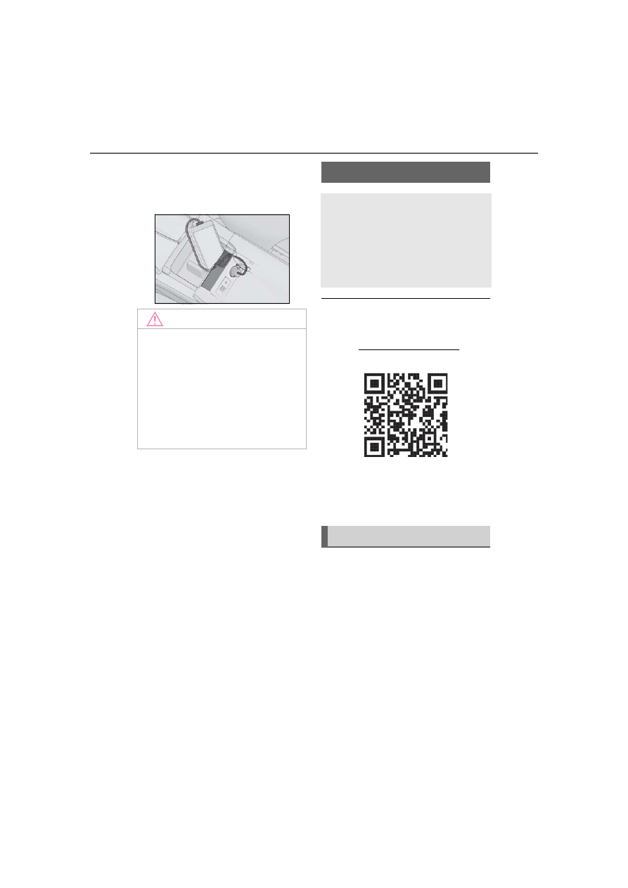
■
Using the power outlet
The shape of the console box partition
allows power cables to be passed through
when the console box lid is partially closed.
■
HomeLink
®
programming procedure
The programming procedures can also be
found at the following URL.
Website: www.homelink.com/lexus
For support, contact customer support at
the following.
Help Line: 1-800-355-3515
The HomeLink
®
wireless control sys-
tem in your vehicle has 3 buttons
which can be programmed to operate
3 different devices. Refer to the pro-
gramming methods on the following
pages to determine the method which
is appropriate for the device.
NOTICE
■
When the power outlet is not in use
To avoid damaging the power outlet,
close the power outlet lid when the
power outlet is not in use. Foreign
objects or liquids that enter the power
outlet may cause a short circuit.
■
To prevent battery discharge
Do not use the power outlet longer than
necessary when the engine is off.
Garage door opener
The garage door opener can be
programmed using the
HomeLink
®
to operate garage
doors, gates, entry doors, door
locks, home lighting systems, secu-
rity systems, and other devices.
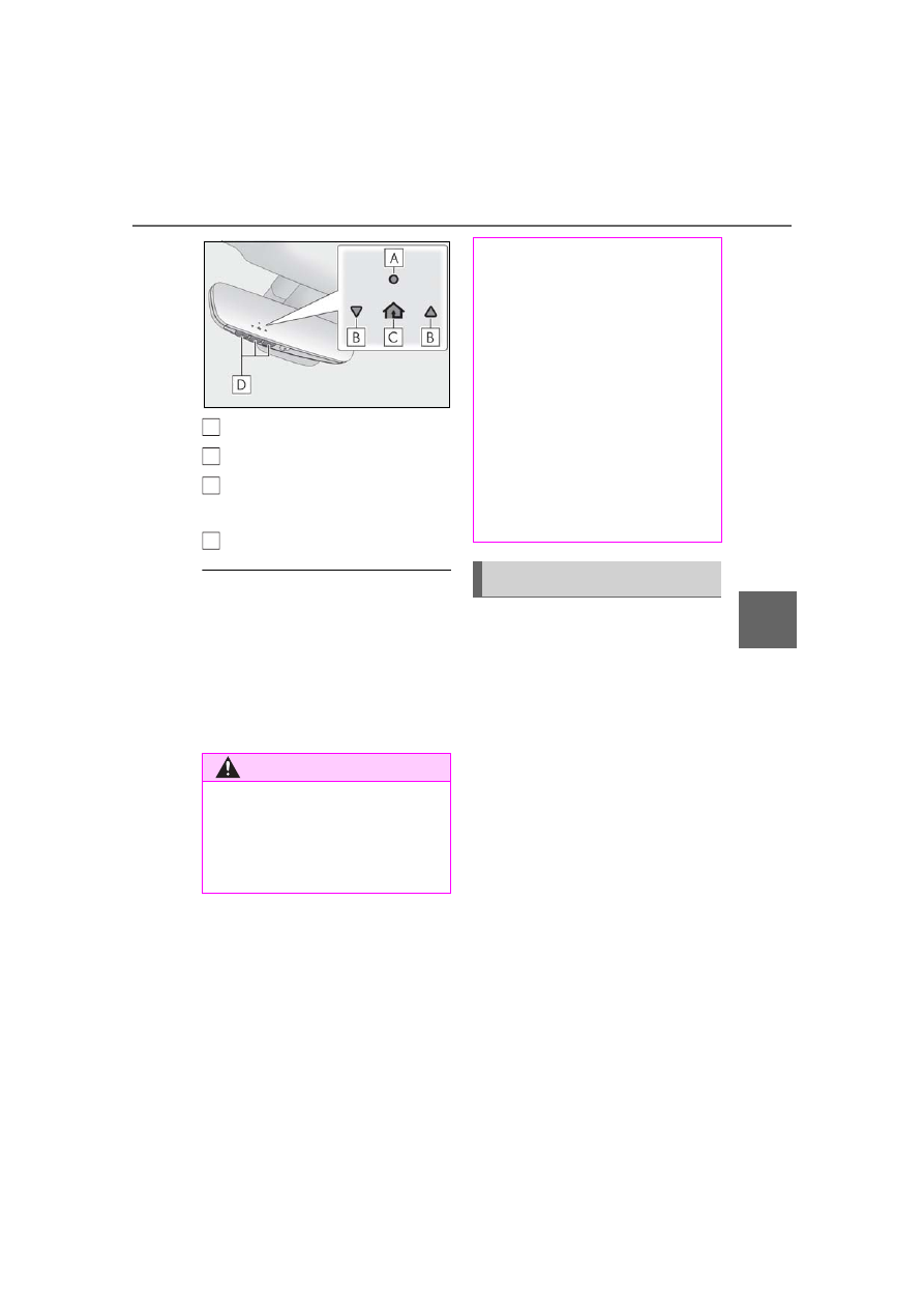
System components
247
5-6. Using the other interior features
5
Interio
r fe
atures
HomeLink
®
indicator light
Garage door operation indicators
HomeLink
®
icon
Illuminates while HomeLink
®
is operating.
Buttons
■
Codes stored in the HomeLink
®
mem-
ory
●
The registered codes are not erased
even if the battery cable is disconnected.
●
If learning failed when registering a dif-
ferent code to a HomeLink
®
button that
already has a code registered to it, the
already registered code will not be
erased.
■
Before programming HomeLink
®
During programming, it is possible
that garage doors, gates, or other
devices may operate. For this rea-
son, make sure that people and
objects are clear of the garage door
or other devices to prevent injury or
other potential harm.
It is recommended that a new bat-
tery be placed in the remote control
transmitter for more accurate pro-
gramming.
Garage door opener motors manu-
factured after 1995 may be
equipped with rolling code protec-
tion. If this is the case, you may need
a stepladder or other sturdy, safe
device to reach the “Learn” or
“Smart” button on the garage door
opener motor.
WARNING
■
When programming a garage door
or other remote control device
The garage door or other device may
operate, so ensure people and objects
are out of danger to prevent potential
harm.
A
B
C
D
■
Conforming to federal safety stan-
dards
Do not use the HomeLink
®
compatible
transceiver with any garage door opener
or device that lacks safety stop and
reverse features as required by federal
safety standards.
This includes any garage door that can-
not detect an interfering object. A door
or device without these features
increases the risk of death or serious
injury.
■
When operating or programming
HomeLink
®
Never allow a child to operate or play
with the HomeLink
®
buttons.
Programming the HomeLink
®
248
5-6. Using the other interior features
■
Programming HomeLink
®
Steps
1
through
3
must be performed
within 60 seconds, otherwise the indi-
cator light will stop flashing and pro-
gramming will not be able to be
completed.
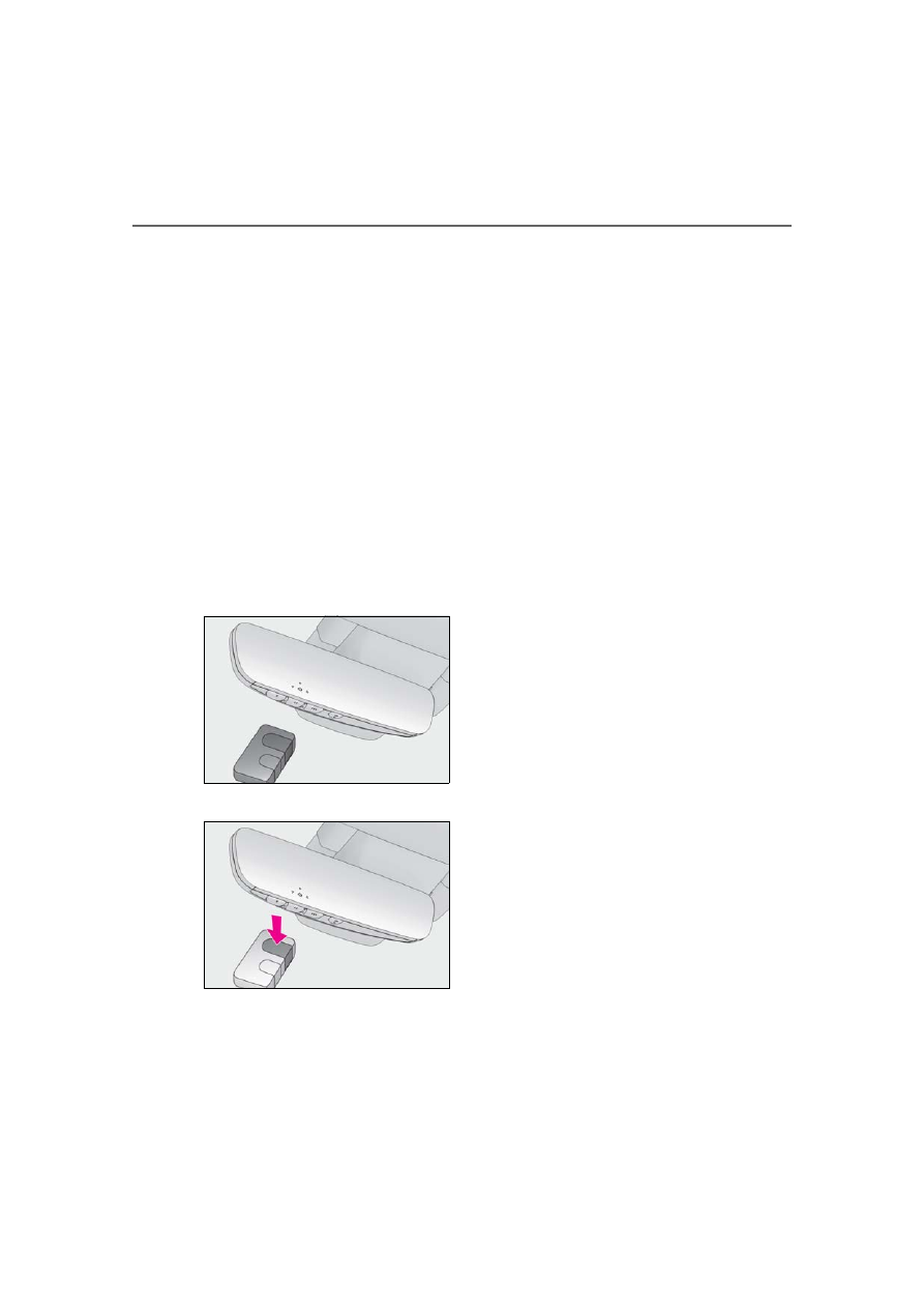
1
Press and release the HomeLink
®
button you want to program and
check that the HomeLink
®
indica-
tor light flashes (orange).
2
Point the remote control transmit-
ter for the device at the rear view
mirror, 1 to 3 in. (25 to 75 mm)
from the HomeLink
®
buttons.
Keep the HomeLink
®
indicator light in
view while programming.
3
Program a device.
Programming a device other than
an entry gate (for U.S.A. owners)
Press and hold the remote control
transmitter button until the
HomeLink
®
indicator light changes
from slowly flashing orange to rapidly
flashing green (rolling code) or contin-
uously lit green (fixed code), then
release the button.
Programming an entry gate (for
U.S.A. owners)/Programming a
device in the Canadian market
Press and release the remote control
transmitter button at 2 second inter-
vals, repeatedly, until the HomeLink
®
indicator light changes from slowly
flashing (orange) to rapidly flashing
(green) (rolling code) or continuously
lit (green) (fixed code).
4
Test the HomeLink
®
operation by
pressing the newly programmed
button and observing the indicator
light:
Indicator light illuminates: Program-
ming of a fixed code device has
completed. The garage door or
other device should operate when a
HomeLink
®
button is pressed and
released.
Indicator light flashes rapidly: The
garage door opener motor or other
device is equipped with a rolling
code. To complete programming,
firmly press and hold the
HomeLink
®
button for 2 seconds
then release it.
If the garage door or other device
does not operate, proceed to “Pro-
gramming a rolling code system”.
Нет комментариевНе стесняйтесь поделиться с нами вашим ценным мнением.
Текст