Defender (1999-2002). Manual — part 43

ENGINE
29
OVERHAUL
10. Remove crankshaft pulley bolt.
11. Fit Woodruff key to crankshaft.
12. Fit oil pump drive chain to rear row of teeth on
crankshaft sprocket i.e. teeth furthest away from
timing mark on sprocket.
13. Fit sprocket to crankshaft ensuring that timing
mark on sprocket is facing towards front end of
crankshaft.
14. Fit oil pump drive sprocket to oil pump and drive
chain ensuring that ’D’ shape on sprocket is
located on flat on oil pump drive shaft.
15. Apply Loctite 242 to threads of oil pump drive
sprocket bolt, fit bolt and tighten to 25 Nm (18
lbf.ft) .
16. Fit timing chain fixed guide, fit bolts and tighten
to:
M6 bolt - 10 Nm (7 lbf.ft)
M10 bolt - 45 Nm (34 lbf.ft)
17. Fit timing chain adjustable guide, fit bolt and
tighten to 25 Nm (18 lbf.ft) .
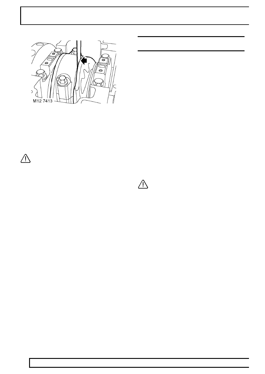
18. Fit camshaft sprocket to timing chain with timing
mark on sprocket between the 2 coloured links,
suitably retain sprocket to chain.
19. Fit timing chain to crankshaft sprocket aligning
coloured link to timing mark on sprocket.
CAUTION: Ensure timing marks are
positioned as shown - No. 1 piston at TDC
firing.
20. Apply an even film film of sealant, Part No. STC
4600 to mating face of timing cover and spread
to an even film using a roller.
CAUTION: Assembly and bolt tightening
must be completed within 20 minutes of
applying sealant.
21. Fit timing cover, fit bolts in their original fitted
positions and working from the centre outwards,
tighten progressively to 27 Nm (20 lbf.ft) .
12
ENGINE
30
OVERHAUL
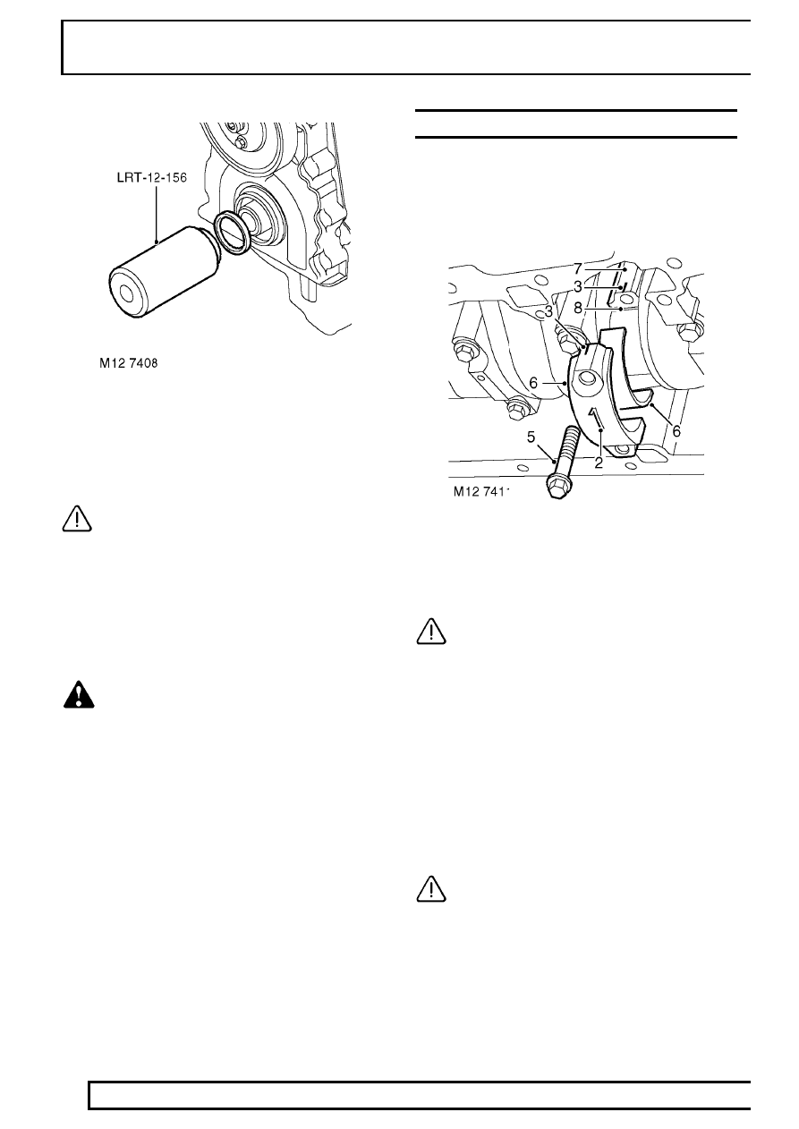
22. Fit oil seal guide, from seal kit, over end of
crankshaft.
23. Fit new oil seal into timing cover using
LRT-12-156.
CAUTION: Oil seal must be fitted dry.
24. Remove LRT-12-156 and oil seal guide.
25. Fit crankshaft pulley, fit crankshaft pulley bolt.
26. Fit LRT-51-003 to crankshaft pulley and secure
with 2 bolts.
27. Using assistance, restrain engine and using a
torque multiplier, tighten crankshaft bolt to 460
Nm (340 lbf.ft) .
WARNING: DUE TO THE HIGH TORQUE
LOADING REQUIRED, IT IS ESSENTIAL
THAT ENGINE IS ADEQUATELY
RESTRAINED.
28. Remove LRT-51-003.
29. Position damper to crankshaft pulley, fit 3 bolts
and tighten to 80 Nm (60 lbf.ft) .
30. Fit sump gasket. See this Section.
31. Fit cylinder head gasket. See this Section.
BEARINGS - CONNECTING RODS
Service repair no - 12.17.16.01
Remove
1. Remove oil pump. See this Section.
2. Mark cylinder reference number on each
connecting rod big-end bearing cap.
3. Make suitable alignment marks between each
big-end bearing cap and connecting rod.
CAUTION: Due to the ’fracture split’
method of manufacturing connecting rods
and bearing caps, incorrect fitting of cap
to connecting rod will damage mating faces and
necessitate replacement of connecting rod
assembly.
4. Rotate crankshaft clockwise until No. 1 big-end
is at BDC.
5. Remove and discard 2 bolts securing No. 1
big-end bearing cap.
6. Remove bearing cap, remove and discard
big-end bearing shell.
7. Push connecting rod up cylinder bore until rod is
clear of crankshaft journal.
CAUTION: Ensure that connecting rod
does not contact cylinder bore or oil squirt
jet and piston does not contact the valves
or EUI’s if the cylinder head is fitted.

ENGINE
31
OVERHAUL
8. Remove and discard big-end bearing shell from
connecting rod.
CAUTION: Engine Serial No. Prefixes 10P
to 14P:- The ’sputter type’ connecting rod
bearings fitted to these engines, identified
by them having a slightly darker colour than the
bearing cap shells should be replaced with the
’plain type’ bearing shells fitted to Engine Serial
No. Prefixes 15P to 19P.
9. Repeat above procedures for remaining big-end
bearings.
CAUTION: Keep bearing caps in their fitted
order.
Inspection
NOTE: If crankshaft is to be removed,
big-end bearing journals should be
checked when crankshaft is inspected.
1. Check each big-end bearing journal for scoring,
wear and ovality, make 3 checks at 120
°
intervals
in centre of journal:
Big-end journal diameter =
54.000
±
0.01 mm (2.125
±
0.0004 in)
CAUTION: Big-end journals may not be
reground undersize,only one size of
big-end bearing shell is available and if
journals are found to be scored, oval or worn,
crankshaft must be replaced. Big-end bearing
shells must be replaced whenever they have been
removed.
Refit
1. Clean connecting rod journals and bearing shell
locations.
2. Lubricate new big-end bearing shells with engine
oil and fit to connecting rods and bearing caps
ensuring that the ’sputter bearings’ are fitted to
the connecting rods.
NOTE: ’Sputter type’ bearing shells can be
identified by them by having a slightly
darker colour.
3. Rotate crankshaft until No. 1 big-end bearing
journal is at BDC.
4. Taking care not to damage oil squirt jet or to
displace bearing shell, pull connecting rod on to
crankshaft journal.
5. Check that bearing shell is correctly located in
big-end bearing cap.
6. Fit No. 1 big-end bearing cap ensuring that
reference marks are aligned.
7. Lightly oil threads of new big-end bearing cap
bolts, fit bolts and tighten to:
Stage 1 - 20 Nm (15 lbf.ft)
Stage 2 - Further 80
°
CAUTION: Do not carry out stages 1 and 2
in one operation.
12
ENGINE
32
OVERHAUL
8. Carefully move connecting rod to one side of
journal and using feeler gauges, measure
end-float of connecting rod on journal:
Connecting rod end-float = 0.2 to 0.5 mm
(0.008 to 0.021 in).
CAUTION: If end-float exceeds limits
given, replace connecting rod and repeat
end-float check - See pistons, connecting
rods and cylinder bores.
9. Repeat above procedures for remaining big-end
bearings.
10. Fit oil pump. See this Section.
PISTONS, CONNECTING RODS AND CYLINDER
BORES
Service repair no - 12.17.02.01
Remove
1. Remove cylinder head gasket. See this
Section.
2. Remove connecting rod bearings. See this
Section.
3. Remove ridge of carbon from top of cylinder
bore.
4. Suitably identify each piston and connecting rod
assembly to its respective cylinder bore.
5. Carefully push connecting rod to top of cylinder
bore taking care that connecting rod does not
contact oil squirt jet or cylinder wall, remove
each piston and connecting rod assembly in
turn.
6. Using a suitable expander, remove and discard
piston rings from pistons.
7. Using a squared off end of an old piston ring,
clean carbon from ring grooves.
8. Clean carbon from piston crown and skirt.
CAUTION: Do not use abrasives on
graphited area of piston skirt, do not use a
wire brush or scraper on any part of the
pistons.
9. Secure connecting rod in a soft jawed vice.
10. Suitably identify each piston to its connecting rod
and fitted position of piston on rod.
11. Using suitable circlip pliers, remove and discard
2 circlips securing gudgeon pin.
12. Push gudgeon pin out of piston and connecting
rod; remove piston.
13. Suitably identify each gudgeon pin to its
respective piston.
14. Repeat above procedures for each piston.
Нет комментариевНе стесняйтесь поделиться с нами вашим ценным мнением.
Текст