Defender (1999-2002). Manual — part 44

ENGINE
33
OVERHAUL
Cylinder bores - Inspection
1. Check cylinder bores for scoring.
2. Measure cylinder bore wear and ovality at a
point 70 mm (2.75 in) from top of each cylinder
bore:
Cylinder bore diameter = 84.460 to 84.442 mm
(3.325 to 3.324 in)
CAUTION: Measurement must be taken
from side to side and front to rear of bore:
CAUTION: Cylinder bore diameter and
ovality must be within limits given above,
no reboring, honing or glaze busting of
cylinder bores is permissible; cylinder block must
be replaced if bores are worn or excessively
scored.
Pistons and connecting rods - Inspection
1. Check each piston for cracks, burning and
damage.
2. Check connecting rods for alignment.
CAUTION: Do not attempt to straighten
misaligned connecting rods.
3. Ensure small-end oil feed holes in connecting
rods are clear.
4. Measure and record diameter of each piston at
right angles to gudgeon pin axis and 46 mm
(1.81 in) from bottom of skirt:
Piston diameter = 84.262 mm
±
0.009 mm
(3.317 in
±
0.0003 in)
CAUTION: Measurement point must be on
the graphited area of the piston.

12
ENGINE
34
OVERHAUL
5. Starting with No. 1 piston, invert piston and with
arrow on piston crown pointing towards REAR of
cylinder block, insert piston into No. 1 cylinder
bore.
6. Position piston with bottom of skirt 25 mm (1.0
in) from top of cylinder bore.
7. Using feeler gauges, measure and record
clearance between piston skirt and LEFT HAND
side of cylinder bore 60 mm (2.4 in) from top of
bore:
Piston to cylinder bore clearance = 0.171 to
0.207 mm (0.007 to 0.008 in)
8. Repeat above procedures for remaining pistons.
CAUTION: Oversize pistons are not
available, if piston to cylinder bore
clearance exceeds limits given, repeat
check using a new piston; if clearances are still
excessive, replace cylinder block.
Piston and 1st compression rings fitted to Engine
Serial No. Prefixes 15P to 19P may be fitted to
Engine Serial No. Prefixes 10P to 14P in engine
sets only. Oil control and 2nd compression rings
are interchangeable between all engines.
9. Check fit of each gudgeon pin in its piston. Pin
must be a tight, sliding fit with no perceptible
side play.
10. Measure gudgeon pin diameter at each end and
centre of pin. Renew gudgeon pin and piston as
an assembly if diameters are less than specified
or if excessive pin to piston side play is evident.
Gudgeon pin diameter = 29.995 to 30.000 mm
(1.180 to 1.181 in)
11. Check connecting rod small-end bushes for
wear, check that gudgeon pin is a sliding fit in
the bush with no perceptible side play.
CAUTION: Small-end bushes cannot be
replaced, a new connecting rod must be
fitted.
ENGINE
35
OVERHAUL
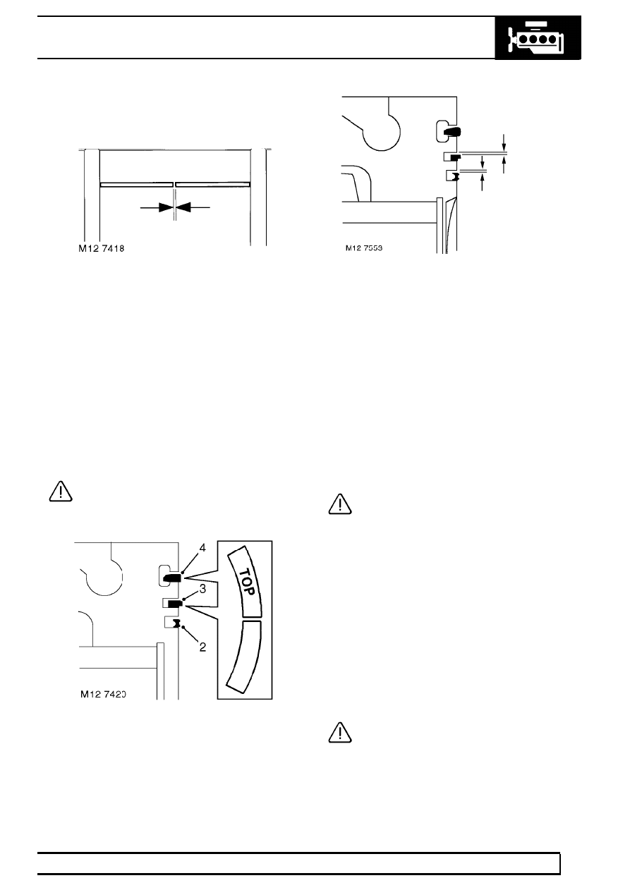
Piston ring gaps - Checking
1. Insert new compression and oil control piston
rings in turn into No. 1 cylinder bore 30 mm (1.25
in) from top of bore and check ring fitted gaps;
ensure rings are kept square to bore when
checking gaps.
1st compression ring fitted gap = 0.30 to 0.40
mm (0.012 to 0.016 in)
2nd compression ring fitted gap = 0.40 to 0.60
mm (0.016 to 0.024 in)
Oil control ring fitted gap = 0.25 to 0.50 mm
(0.01 to 0.02 in)
Repeat for each cylinder bore in turn.
CAUTION: Ensure rings are suitably
identified with the cylinder bore in which
they were checked and are fitted to the
piston for that bore.
2. Fit oil control expander and ring to piston.
3. Fit 2nd compression ring with ’TOP’ marking
upwards.
4. Fit 1st compression ring with ’TOP’ marking
upwards.
5. Check piston ring to groove clearance:
1st compression ring - Not measured
2nd compression ring = 0.050 to 0.082 mm
(0.02 to 0.003 in)
Oil control ring = 0.050 to 0.082 mm (0.02 to
0.003 in)
Pistons and connecting rods - Assembling
1. Lubricate gudgeon pin, gudgeon pin holes in
piston and small-end bush with engine oil.
2. Position piston to its respective connecting rod
with arrow on piston crown on the same side as
the cast boss on the connecting rod.
3. Fit gudgeon pin to its respective piston and
connecting rod; secure with new circlips.
CAUTION: Ensure circlips are fully seated
in their grooves.
4. Repeat above procedures for remaining pistons.
5. Lubricate piston rings and cylinder bores with
engine oil.
6. Check that rings are free to rotate, position ring
gaps at 120
°
to each other and away from the
thrust - LH side of piston - viewed from front of
piston.
7. Using a suitable piston ring clamp, compress
piston rings.
8. Insert connecting rod and piston into its
respective cylinder bore, ensuring that the arrow
on piston crown and the cast boss on connecting
rod are facing towards the front of the cylinder
block.
CAUTION: Ensure that connecting rod
does not contact cylinder bore or oil squirt
jet. Do not pull connecting rod fully down
cylinder bore at this stage.

12
ENGINE
36
OVERHAUL
9. Check that the cut-out in piston skirt is
positioned above the oil squirt jet.
10. Repeat for other pistons in turn ensuring that
pistons and connecting rods are fitted in cylinder
bores from which they were removed.
11. Fit connecting rod bearings. See this Section.
CAUTION: If new pistons, connecting rods
or crankshaft have been fitted, it will be
necessary to select correct thickness of
cylinder head gasket. See this Section.
CRANKSHAFT
Service repair no - 12.21.33.01
Remove
1. Remove timing chain and sprockets. See this
Section.
2. Remove crankshaft rear oil seal. See this
Section.
3. Remove connecting rod bearings. See this
Section.
4. Check that cylinder reference number is on each
main bearing cap. Make suitable alignment
marks between each main bearing cap and
cylinder block.
5. Starting at No. 3 main bearing cap and working
outwards, progressively loosen, then remove 2
bolts securing each cap. Discard main bearing
cap bolts.
Нет комментариевНе стесняйтесь поделиться с нами вашим ценным мнением.
Текст