Defender (1999-2002). Manual — part 89
BRAKES
3
REPAIR
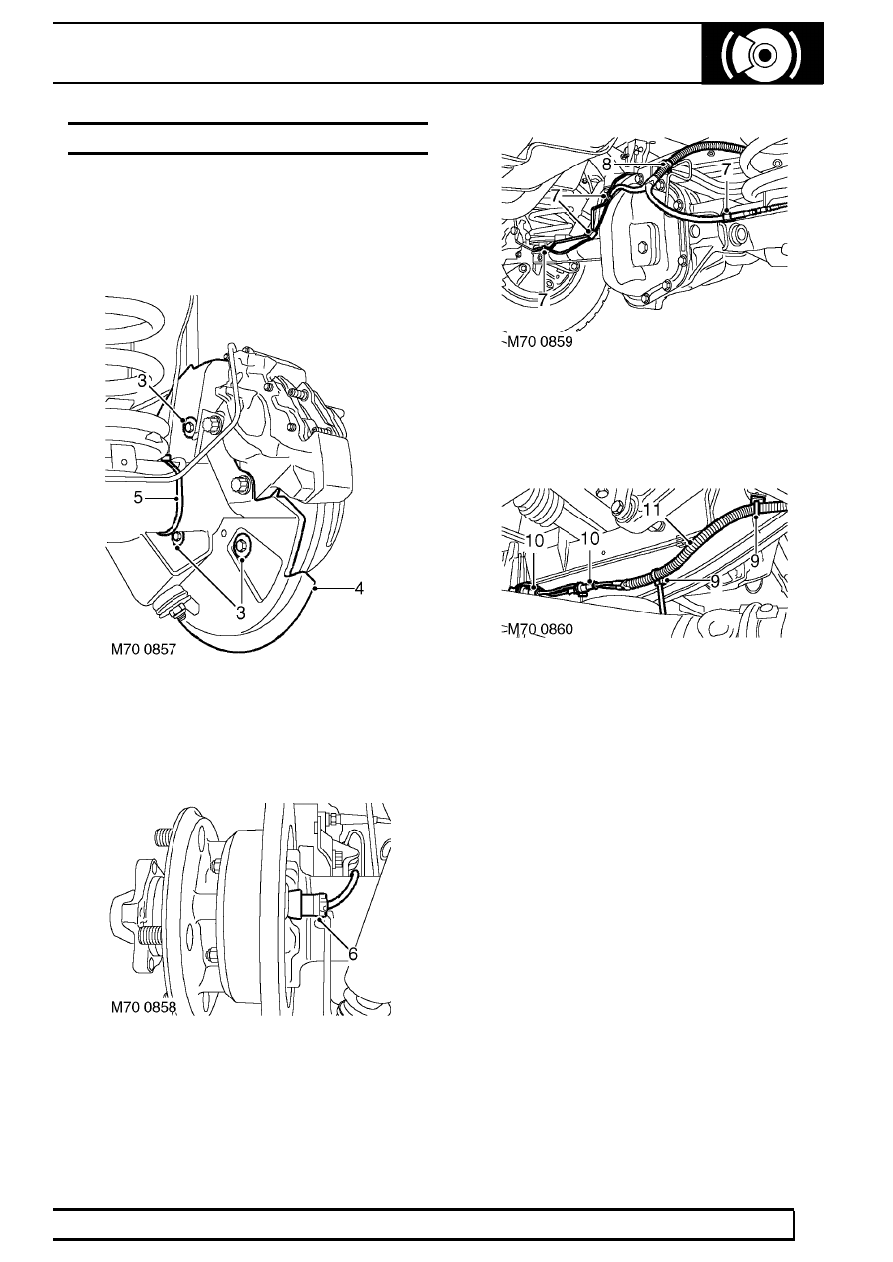
SENSORS - ABS - REAR WHEELS
Service repair no - 70.65.31
Remove
1. Raise vehicle on a 2 post ramp.
2. Remove both rear wheels.
3. Remove 3 bolts securing each brake disc
backplate to hub assemblies.
4. Remove both back plates.
5. Remove 2 cable ties securing sensor harness to
outer ends of axle.
6. Carefully prise both sensors from hub
assemblies.
7. Release 4 clips securing sensor harness to axle.
8. Release cable tie securing harness to
differential.
9. Release 3 cable ties securing harness to chassis
longitudinal.
10. Disconnect sensor multiplug.
11. Remove harness and sensor assembly.
Refit
12. Position harness and sensor assembly to vehicle
and connect multiplug.
13. Apply grease to both sensors.
14. Carefully fit both sensors to hub assemblies.
15. Secure harness to axle and differential with
cable ties.
16. Secure harness to axle with clips.
17. Secure harness to chassis with cable ties.
18. Fit both back plates to hub assemblies and
secure with bolts.
19. Fit rear wheels and tighten to 130 Nm (95 lbf.ft)
.
20. Lower vehicle.

70
BRAKES
4
REPAIR
MASTER CYLINDER
Service repair no - 70.30.08
Remove
1. Disconnect battery negative lead.
2. Place a container under the master cylinder to
collect any brake fluid spillage.
CAUTION: Do not allow brake fluid to
contact paint finished surfaces as paint
may be damaged. If spilled, remove fluid
and clean area with clean warm water.
3. Clean area around master cylinder ports.
4. Loosen 2 unions securing brake pipes to master
cylinder ports.
5. Disconnect both brake pipes from master
cylinder. Cover, not plug, pipe ends to prevent
entry of dirt.
6. Disconnect 2 Lucars from reservoir cap.
7. Remove 2 nuts securing master cylinder to
brake servo.
8. Withdraw master cylinder from servo and
remove.
Do not carry out further dismantling if
component is removed for access only.
9. Carefully ease reservoir from master cylinder by
rolling it from seals.
10. Remove seals from master cylinder.
NOTE: Master cylinder to reservoir seals
are different sizes.
11. Fit NEW seals to master cylinder, ensuring seals
are fitted to correct ports.
12. Fit reservoir to master cylinder.
Refit
13. Ensuring that water ingress seal is in position, fit
master cylinder to servo.
14. Fit nuts securing master cylinder to servo and
tighten to 26 Nm (19 lbf.ft) .
15. Connect brake pipes to master cylinder and
tighten unions to 15 Nm (11 lbf.ft) .
16. Connect Lucars to reservoir cap.
17. Fill reservoir with recommended brake fluid. See
LUBRICANTS, FLUIDS AND CAPACITIES,
Information.
18. Bleed the brake system. See Adjustment.
19. Reconnect battery negative lead.

BRAKES
5
REPAIR
SERVO ASSEMBLY
Service repair no - 70.50.01
Remove
Before starting, refer to general brake service
practice. See Adjustment.
NOTE: The non-return valve and grommet
are the only serviceable components. In
event of failure or damage, fit a new unit.
1. Remove master cylinder. See this Section.
2. Release vacuum hose from servo.
3. Disconnect brake light switch Lucars.
4. Remove 3 screws securing closing panel to
lower ’A’ post.
5. Release closing panel sufficient to gain access
to brake pedal return springs.
6. Release 2 brake pedal return springs from brake
pedal.
7. Remove blanking grommets from either side of
pedal box.
8. Remove split pin and clevis pin securing servo
push rod to brake pedal.
9. Remove 2 nuts securing servo to pedal box.
10. Remove servo assembly and rubber washer
from pedal box.

70
BRAKES
6
REPAIR
Refit
11. Fit rubber washer and servo assembly to pedal
box.
12. Fit nuts securing servo to pedal box and tighten
to 14 Nm. (10 lbf.ft)
13. Position brake pedal to servo push rod.
14. Fit clevis pin and NEW split pin to secure brake
pedal to servo push rod.
15. Fit blanking grommets to each side of pedal box.
16. Attach pedal return springs to brake pedal.
17. Position closing panel and tighten screws to
lower ’A’ post.
18. Connect vacuum hose to servo.
19. Connect brake switch Lucars.
20. Fit brake master cylinder. See this Section.
MODULATOR UNIT - ABS
Service repair no - 70.65.49
Remove
1. Position cloth under modulator to absorb any
fluid spillage.
CAUTION: Do not allow brake fluid to
contact paint finished surfaces as paint
may be damaged. If spilled, remove fluid
and clean area with clean warm water.
2. Disconnect 2 inlet brake pipe unions from pump
side of modulator.
3. Disconnect 4 outlet brake pipe unions from top
of modulator.
CAUTION: Plug the connections.
4. Disconnect 2 multiplugs from rear of modulator.
5. Loosen nut securing rear of modulator to
mounting bracket.
6. Remove 2 nuts securing front of modulator to
mounting bracket.
7. Release modulator from mounting bracket.
8. Disconnect multiplug from base of modulator.
9. Remove modulator.
Do not carry out further dismantling if
component is removed for access only.
10. Remove 3 mounting rubbers from old modulator
and fit to new.
Нет комментариевНе стесняйтесь поделиться с нами вашим ценным мнением.
Текст