Defender (1999-2002). Manual — part 88
BRAKES
1
ADJUSTMENT
BRAKE SYSTEM BLEED
Service repair no - 70.25.02
Preparation
WARNING: Before bleeding the brake
system refer to general brake service
practice. See this Section. general brake
service practice
•
During bleed procedure, brake fluid level must
not be allowed to fall below the MIN mark. Keep
reservoir topped up to the MAX mark.
•
To bleed the hydraulic circuits, four bleed
nipples are provided, one at each caliper.
There are two methods by which air can be removed
from the braking system:-
1. MANUAL BLEED PROCEDURE
2. PRESSURE BLEED PROCEDURE
Pressure bleed procedure
Purpose designed equipment for pressure filling and
bleeding of hydraulic systems may be used on Land
Rover vehicles. The equipment manufacturers
instructions must be followed and the pressure must
not exceed 4.5 bar, 65 lb/in.
Manual bleed procedure
Equipment required
•
Clean glass receptacle
•
Bleed hose
•
Wrench
•
Approx. 2 litres (3 pts) brake fluid
Master cylinder bleed
1. Disconnect battery negative lead.
2. Depress brake pedal fully and slowly 5 times.
3. Release pedal and wait 10 seconds.
4. Repeat until firm resistance is felt at the pedal.
Complete circuit bleed
1. Disconnect battery negative lead.
2. Fit bleed hose to caliper bleed screw.
3. Dip free end of bleed hose into brake fluid in
bleed bottle.
4. Open bleed nipple.
5. Depress brake pedal fully several times until fluid
is clear of air bubbles.
6. Keeping pedal fully depresses, tighten bleed
nipple then release pedal.
7. Repeat procedure for remaining calipers.
8. Fit bleed screw protection caps.
9. Check/top-up fluid level when bleeding is
complete.

70
BRAKES
2
ADJUSTMENT
PARK BRAKE - ADJUST
Service repair no - 70.45.09
Check
NOTE: The park brake should be fully
operational on third notch of ratchet.
1. Raise one rear wheel clear of ground and
support on axle stand.
2. Release park brake lever.
3. Tighten brake adjuster to 25 Nm (18 lbf.ft) to
fully expand shoes to drum.
4. Back off adjuster 1
1
/
2
turns, check that drum is
free to rotate.
5. Check operation of park brake lever to give pawl
2 notches free movement on ratchet before
being fully operational on third notch of ratchet.
Adjust park brake accordingly if lever travel
exceeds the above tolerance.
CAUTION: Cable adjustment must ONLY
be used for initial setting and to
compensate for cable stretch. It MUST
NOT be used to take up brake shoe wear, which
MUST be adjusted at brake drum.
6. Remove axle stand and wheel chock.
BRAKES
1
REPAIR
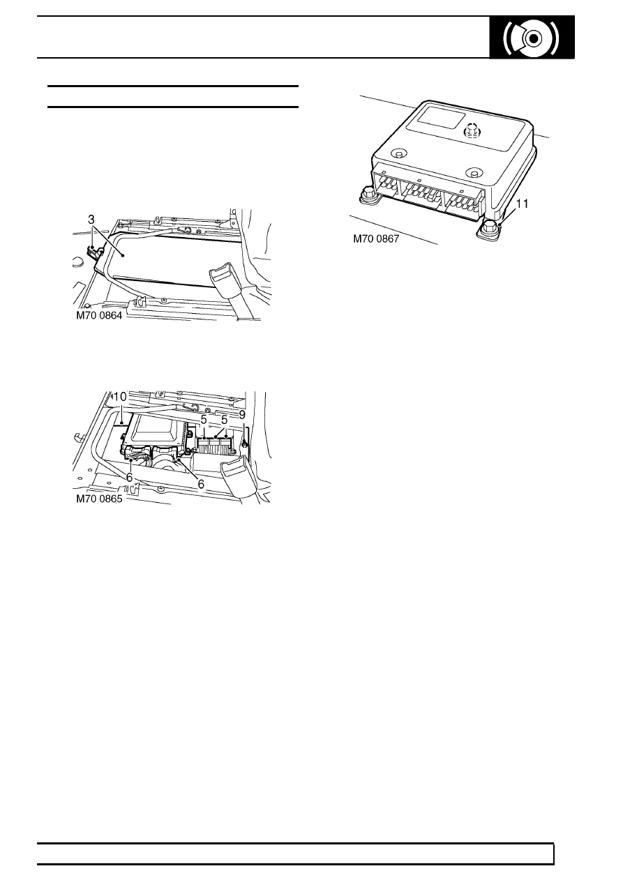
ECU - ABS
Service repair no - 70.65.01
Remove
1. Disconnect battery negative lead.
2. Release and remove passenger seat base.
3. Release clip securing ECU cover plate.
4. Remove ECU cover plate.
5. Disconnect 3 multiplugs from ABS ECU.
6. Disconnect 2 multiplugs from engine
management ECU.
7. Release seat base carpet to gain access to ECU
mounting plate Torx screws.
8. Remove 2 Torx screws securing front edge of
ECU mounting plate.
9. Remove nut securing rear edge of ECU
mounting plate.
10. Remove mounting plate and ECU assembly from
seat base.
11. Remove 3 bolts securing ABS ECU to mounting
plate.
12. Remove ABS ECU.
Refit
13. Position ABS ECU to mounting plate and secure
with bolts.
14. Fit mounting plate and ECU assembly to seat
base.
15. Fit Torx screws and nut securing mounting plate
to seat base.
16. Re-position carpet.
17. Connect multiplugs to ABS and engine
management ECU’s.
18. Fit ECU cover plate to seat base and secure in
position with clip.
19. Fit passenger seat base.
20. Reconnect battery negative lead.
70
BRAKES
2
REPAIR
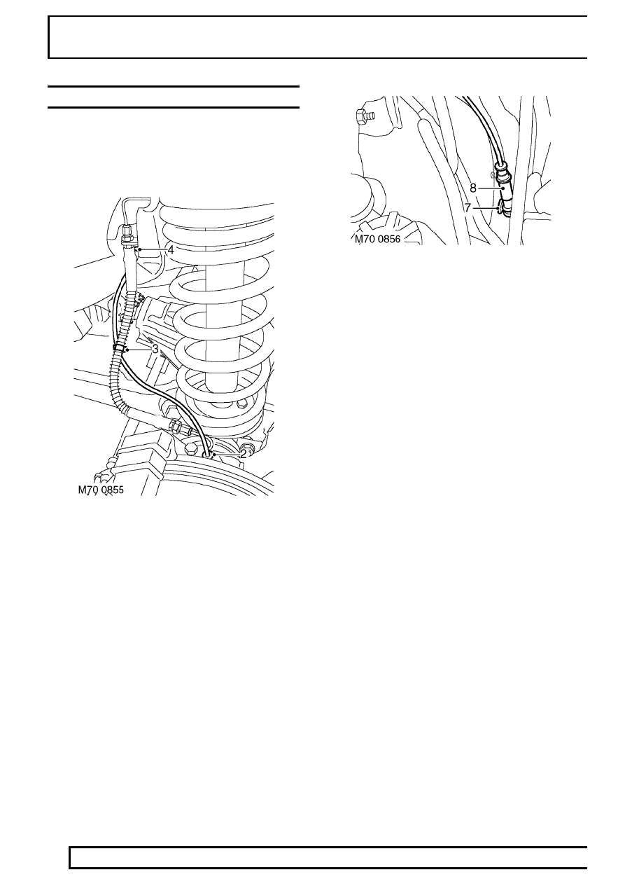
SENSOR - ABS - FRONT WHEEL
Service repair no - 70.65.30
Remove
1. Raise vehicle on a 2 post ramp.
2. Carefully prize ABS sensor from front hub.
3. Release clip securing ABS sensor harness to
brake pipe.
4. Release clip securing ABS sensor harness to
inner wing.
5. Lower vehicle.
6. Release second clip securing ABS harness to
inner wing.
7. Disconnect sensor harness multiplug.
8. Remove sensor and harness.
Refit
9. Connect sensor harness multiplug.
10. Position sensor harness and secure to inner
wing with clip.
11. Raise vehicle.
12. Secure harness to inner wing and brake pipe
with clips.
13. Apply grease to sensor.
14. Carefully fit sensor to hub assembly.
15. Lower vehicle.
Нет комментариевНе стесняйтесь поделиться с нами вашим ценным мнением.
Текст