Defender. Manual — part 22
Rear Suspension - Upper Arm
Removal and Installation
Removal
1. Support rear of chassis on stands, allow axle to hang freely.
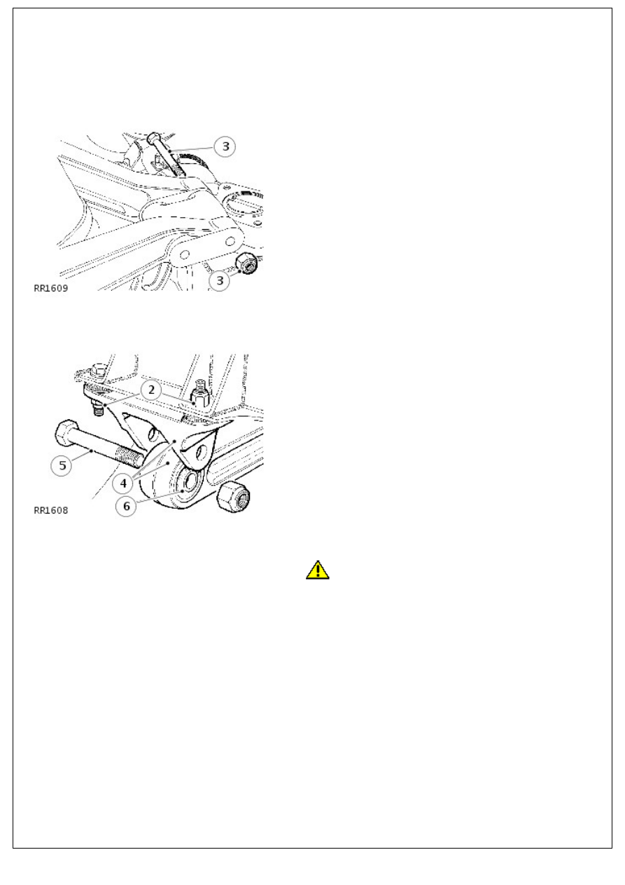
2. Remove fixings securing upper arm bracket to frame.
3. Remove fixings securing upper arms to pivot bracket.
4. Remove upper arm, complete with frame bracket.
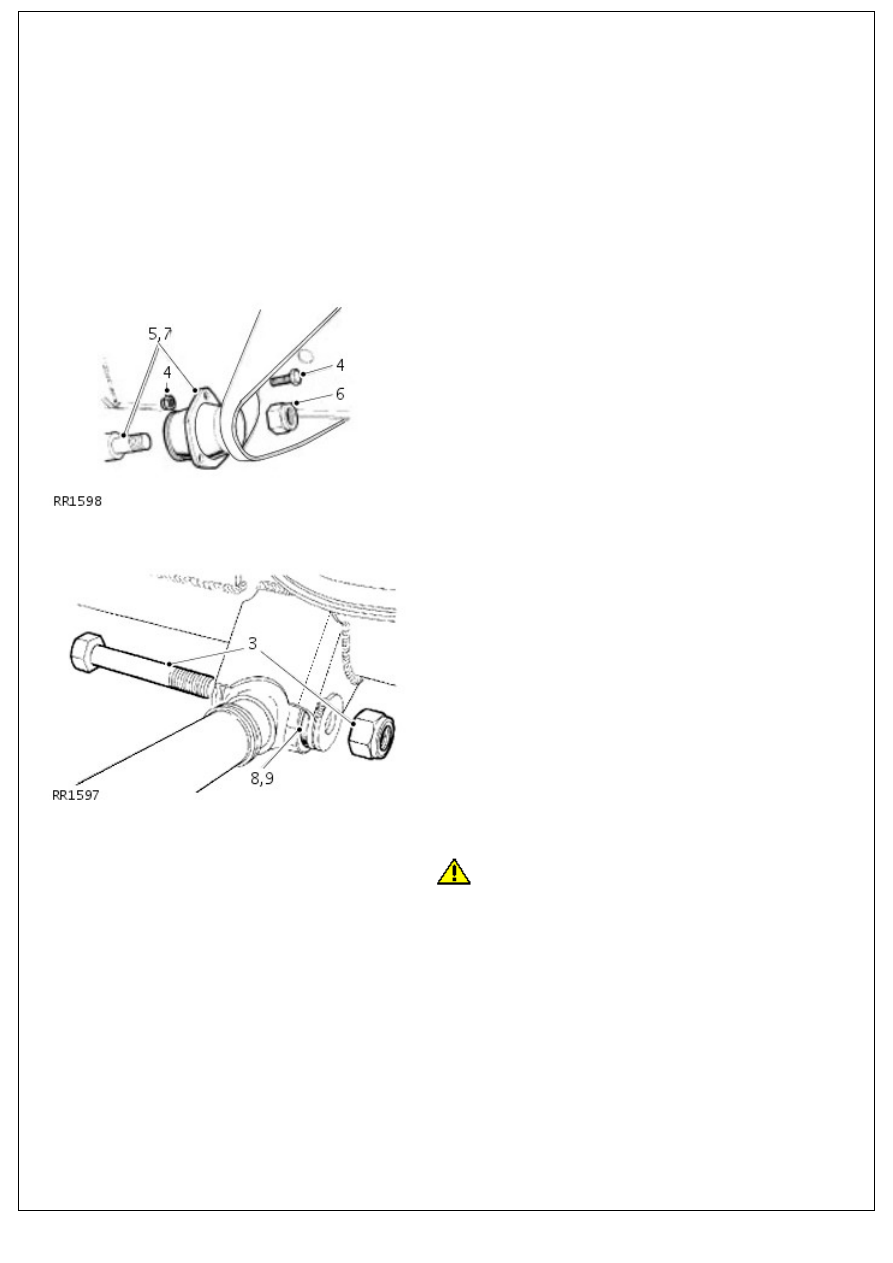
5. Remove bolt.
6. Separate upper arm from bracket.
7. Renew bush
8. Press out rubber bushes.
9.
CAUTION: Apply pressure to outer edge of bush, and
not rubber inner.
Fit bush centrally in housing.
Installation
1. NOTE: Do not fully tighten fixings until all components are in
position.
Secure upper arm to frame bracket.
2. Fit upper arm to pivot bracket and tighten fixings to 115 Nm
(84 lbf/ft).
3. Fit frame bracket to chassis mounting.
4. If you are fitting a new nut to the upper arm bolt, fully
tighten to 115 Nm (84 lbf/ft). If you are refitting an existing
nut, then tighten to 176 Nm (130 lbf/ft).
Rear Suspension - Lower Arm
Removal and Installation
Removal
1. Site vehicle on a ramp .
2. Alternatively, support vehicle on stands under rear axle.
3. Remove lower arm rear fixings.
4. Remove mounting bracket fixings at side member bracket.
5. Remove lower arm complete.
6. Remove locknut.
7. Remove mounting bracket from lower arm.
8. Renew bush
9. Press out rubber bushes.
Installation
1.
CAUTION: Apply pressure to outer edge of bush, and
not rubber inner.
Fit bush centrally in housing.
2. Fit mounting rubber to lower arm.
3. Secure mounting rubber to chassis bracket, but do not fully
tighten locknut.
4. Fit lower arm to axle mounting and secure fixing to 176 Nm
(130 lbf/ft).
5. Lower vehicle, allow axle to take up static laden position,
and fully tighten lower arm to chassis fixing to 176 Nm (130
lbf/ft).
Rear Suspension - Axle Bump Stop
Removal and Installation
Removal
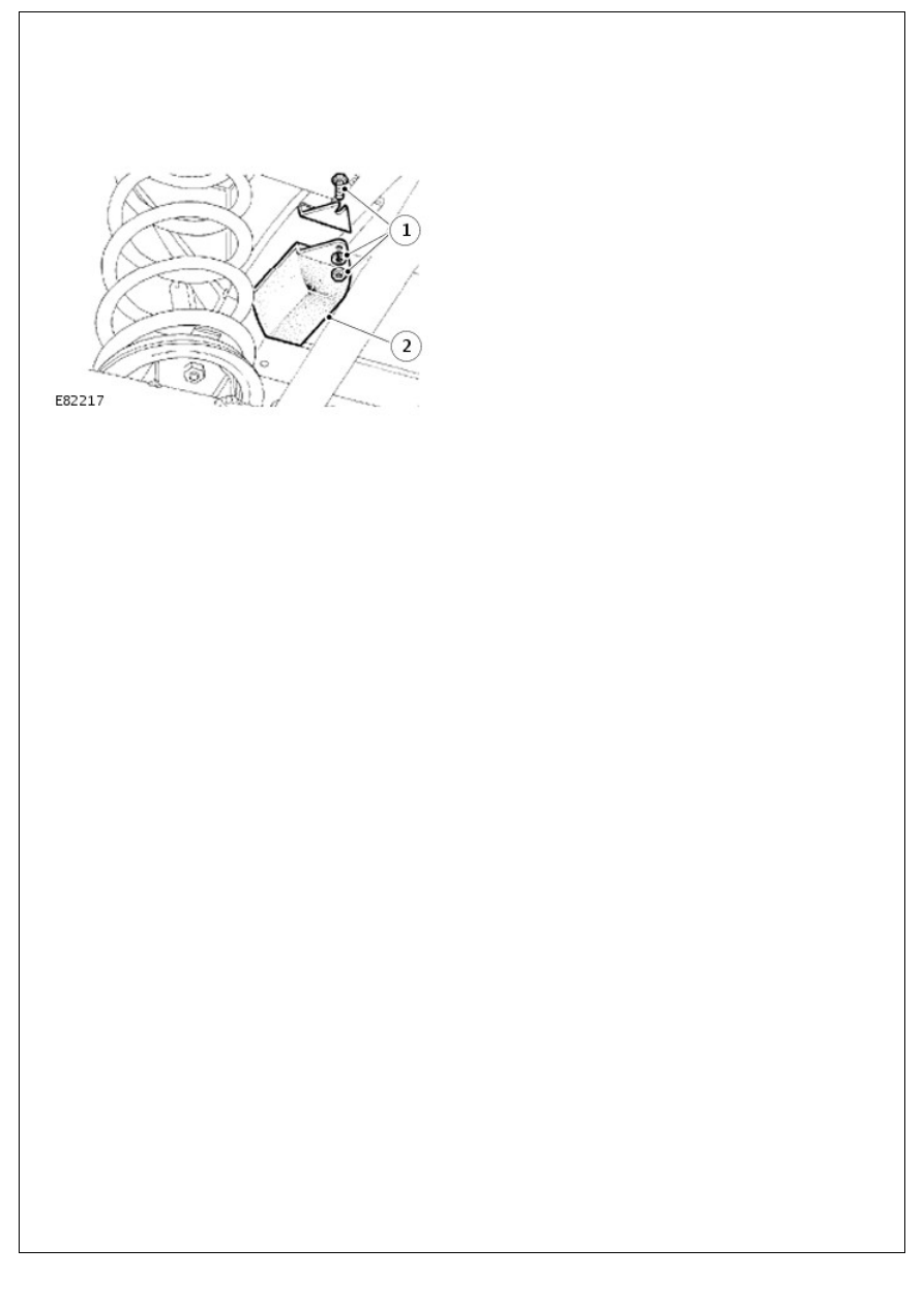
1. Remove fixings.
2. Remove bump stop.
Installation
1. Position bolts in slots in bracket.
2. Install bump stop, secure with washers and nuts.
Wheels and Tires -
Wheels - 90 Models
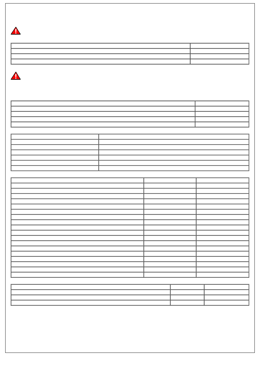
WARNING: Always use the same make and type of radial-ply tyres, front and rear. DO NOT use cross-ply tyres, or
interchange tyres from front to rear.
Wheel type
Wheel size
Steel wheel - UK and Western Europe
6F x 16
Steel wheel - Other markets
5.5F x 16
Alloy wheel
7J x 16
Wheels
WARNING: Always use the same make and type of radial-ply tyres, front and rear. DO NOT use cross-ply tyres, or
interchange tyres from front to rear.
If the wheel is marked 'TUBED' , an inner tube MUST be fitted, even with a tubeless tire. If the wheel is marked
'TUBELESS', an inner tube must NOT be fitted.
Wheel type
Wheel size
Steel wheel - UK and Western Europe
6F x 16
Steel wheel - Other markets except Japan
5.5F x 16
Steel wheel - Japan
6.5J x 16
Alloy wheel
7J x 16
Tire sizes
Model
Tire size
90
205/80 R16 Radial
265/75 R16 Radial (Multi terrain)
7.50 R16 Radial
110 - except Japan
7.50 R16 Radial
110 Japan
7.50 R16C
130
7.50 R16 radial
Tire pressures
Model - Tire size
Front
Rear
90 - 205/80 R16
1,9 bar
2,6 bar
28 lbf/in!
38 lbf/in!
2,0 kgf/cm!
2,7 kgf/cm!
90 - 265/75 R16
1,9 bar
2,4 bar
28 lbf/in!
35 lbf/in!
2,0 kgf/cm!
2,7 kgf/cm!
90 - 7.50 R16
1,9 bar
2,6 bar
28 lbf/in!
38 lbf/in!
2,0 kgf/cm!
2,7 kgf/cm!
110 - 7.50 R16 (except Japan)
1,9 bar
3,3 bar
28 lbf/in!
48 lbf/in!
2,0 kgf/cm!
3,4 kgf/cm!
110 - 7.50 R16C (Japan)
2,2 bar
4,1 bar
32 lbf/in!
60 lbf/in!
2,3 kgf/cm!
4,3 kgf/cm!
130 - 7.50 R16
3,0 bar
4,5 bar
44 lbf/in!
65 lbf/in!
3,1 kgf/cm!
4,6 kgf/cm!
Road Wheel Nut Torque Specifications
Wheel type
Nm
lb-ft
*Steel wheels
100
80
Alloy wheels
130
96
Heavy duty wheels
170
125
* Wheel nuts must be tightened by diagonal selection
Нет комментариевНе стесняйтесь поделиться с нами вашим ценным мнением.
Текст