Defender. Manual — part 38
10. Bleed brakes.
For additional information, refer to:
Brake System Bleeding
(206-00 Brake System - General Information, General
Procedures).
11. Depress brake pedal to seat pads onto discs.
12. Install road wheels, remove axle stands and tighten nuts to
130 Nm (96 lbf.ft).

Rear Disc Brake - Brake Disc
Removal and Installation
Removal
1. Remove rear wheel bearing and hub assembly.
For additional information, refer to:
Wheel Bearing and Wheel
Hub
(204-02 Rear Suspension, Removal and Installation).
2. Remove disc bolts.
3. Remove disc from rear hub.
Installation
1. Install disc to rear hub.
2. Install disc bolts. Tighten to 73 Nm (54 lbf.ft).
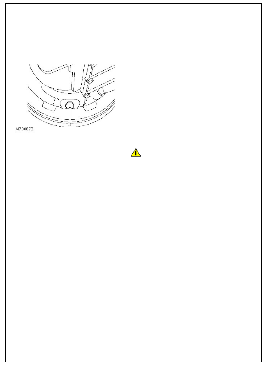
3. Check total disc run out, this must not exceed 0,15 mm
(0.006 in). If necessary reposition disc.
4. Install rear wheel bearing and hub assembly.
For additional information, refer to:
Wheel Bearing and Wheel
Hub
(204-02 Rear Suspension, Removal and Installation).
5. Disc reclamation.
6. NOTE: The brake disc MUST BE renewed if the minimum
running thickness stamped on the disc is recorded.
Check disc thickness. This dimension may be machined to
minimum thickness of 12 mm. Machine equal amounts off
each face.
Parking Brake and Actuation - Parking Brake Shoe and Lining Adjustment
General Procedures
• NOTE: The parking brake should be fully operational on third notch of ratchet.
1. Raise one rear wheel clear of ground and support on axle
stand.
2. Release parking brake lever.
3. Tighten brake adjuster to 25 Nm (18 lbf.ft) to fully expand
shoes to drum.
4. Back off adjuster 1! turns, check that drum is free to
rotate.
5.
CAUTION: Cable adjustment must ONLY be used for
initial setting and to compensate for cable stretch. It MUST NOT
be used to take up brake shoe wear, which MUST be adjusted
at brake drum.
Check operation of parking brake lever to give pawl 2 notches
free movement on ratchet before being fully operational on
third notch of ratchet. Adjust parking brake accordingly if
lever travel exceeds the above tolerance.
6. Remove axle stand and wheel chock.
Parking Brake and Actuation - Parking Brake Cable
Removal and Installation
Removal
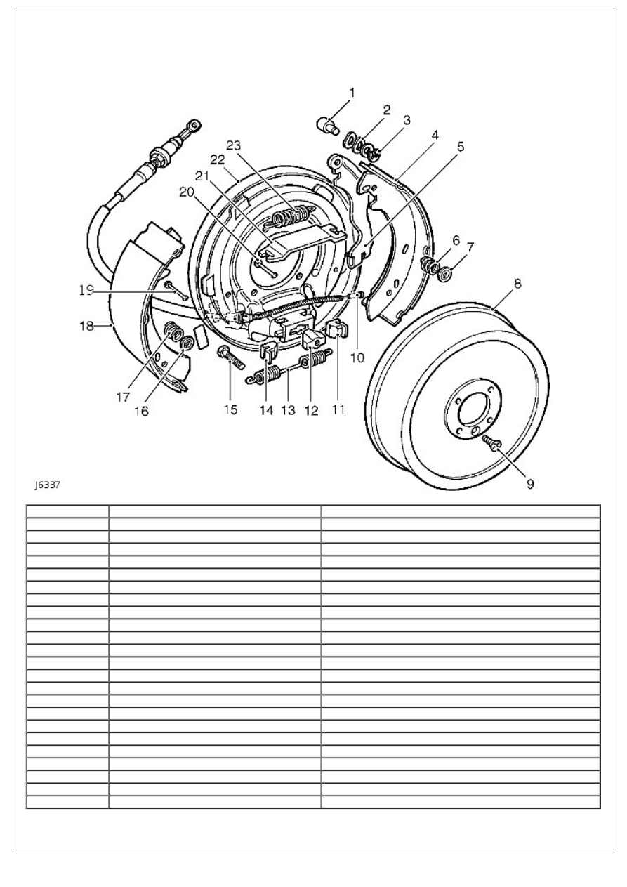
Item
Part Number
Description
1
-
Pin
2
-
Washer
3
-
'C' Circlip
4
-
Brake shoe
5
-
Cable lever
6
-
Hold down spring
7
-
Dished washer
8
-
Brake drum
9
-
Screw
10
-
Brake cable
11
-
Adjuster slide
12
-
Adjuster nut
13
-
Spring
14
-
Adjuster slide
15
-
Adjuster bolt
16
-
Dished washer
17
-
Hold down spring
18
-
Brake shoe
19
-
Hold down pin
20
-
Hold down pin
21
-
Abutment plate
22
-
Back plate
23
-
Spring
1. Park vehicle on level ground, chock road wheels and release
parking brake. Alternatively, raise vehicle on ramp.
Нет комментариевНе стесняйтесь поделиться с нами вашим ценным мнением.
Текст