Defender. Manual — part 39

2. Remove 3 trim studs and lift up parking brake gaiter.
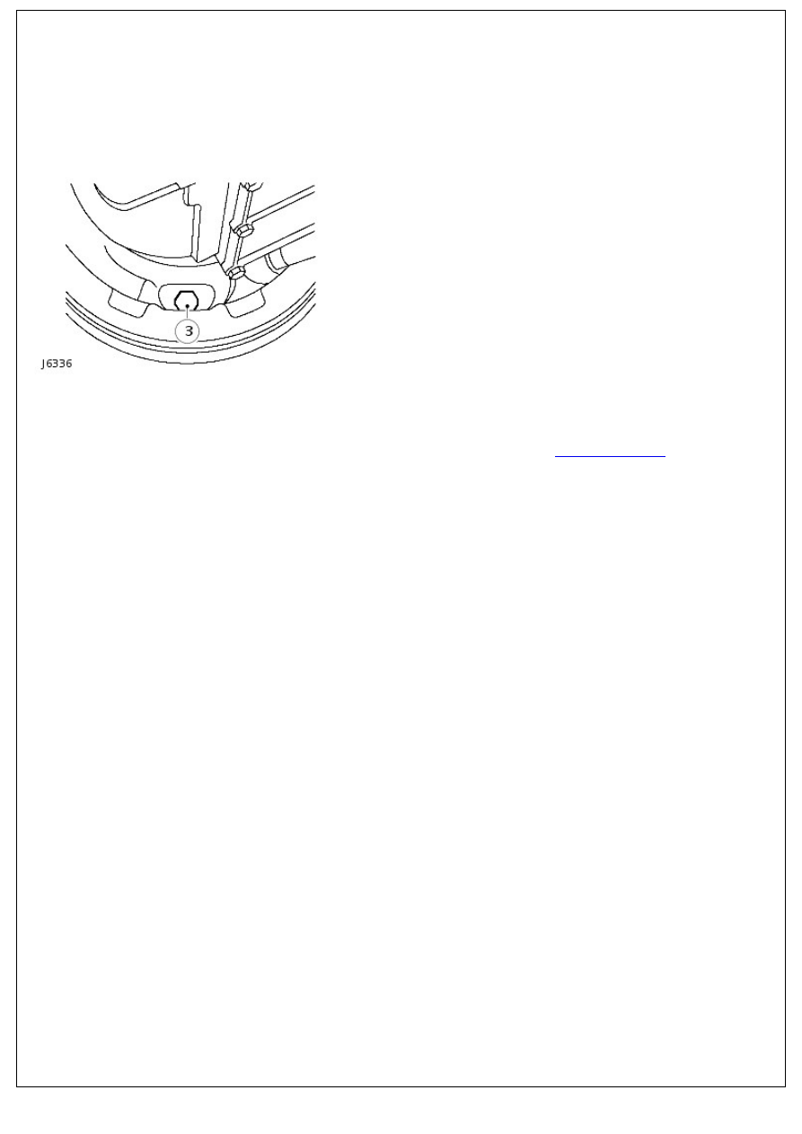
3. Remove split pin, clevis pin, washer and disconnect cable
from parking brake lever.
4. Slacken off transmission brake drum adjusting screw.
5. Disconnect drive shaft from output flange.
6. Remove retaining screw and withdraw brake drum.
7. Release parking brake cable clevis from abutment on cable
lever, see J6337, and pull through aperture in back plate.
8. Pull cable from heelboard and remove from vehicle.
Installation
1. Feed new cable through heelboard ensuring rubber grommet
is correctly located.
2. Position cable over guide plate, insert through backplate and
connect to cable lever.
3. Instal cable to parking brake lever and secure with clevis pin
and split pin.
4. Instal parking brake gaiter.
5. Instal brake drum. Tighten screw to 25 Nm (18 lbf.ft).
6. Screw in and tighten adjuster bolt until brake drum will not
rotate by hand.
7. Tighten adjuster bolt further to 25 Nm (18 lbf.ft) to ensure
brake drum is locked.
8. Slacken off adjuster bolt by 1.5 turns to give brake shoes
running clearance. Check that the drum is free to rotate.
9. Slacken locknut and adjust cable to give the parking brake
pawl two notches free movement on the rachet before
being fully operational on third notch (brake shoes are fully
expanded against drum).
• NOTE: Cable adjustment is for a new cable or to compensate for cable stretch. Cable adjustment must not be used to
take up brake shoe wear.
10. Instal drive shaft to output flange. Tighten fixings to 46 Nm
(34 lbf.ft).
11. Remove wheel chocks and check operation of parking
brake.
Parking Brake and Actuation - Shoes
Removal and Installation
Removal
1. Park vehicle on level ground, chock road wheels and release
parking brake. Alternatively, raise vehicle on a ramp.
2. Disconnect rear propeller shaft from transmission output
flange at brake drum.
3. Slacken off parking brake drum adjustment bolt.
4. Remove single screw securing brake drum to output flange.
5. Withdraw drum to expose brake assembly.
6. Release top and bottom springs from brake shoes, see
J6337.
For additional information, refer to:
Parking Brake Cable
(206-05 Parking Brake and Actuation, Removal and
Installation).
7. Grip dished washer with a pair of pliers, depress washer and
turn through 90°.
8. Remove dished washer, complete with hold down spring and
pin from both shoes.
9. Move brake shoes out from adjuster slides, release from
abutment plate and remove from backplate.
10. Check that springs are satisfactory for continued use. If
new brake shoes are to be fitted, the springs should also be
renewed.
Installation
1. Locate RH brake shoe in slide and secure brake shoe and
lever assembly to backplate with hold down pin, spring and
dished washer.
2. Locate LH brake shoe in slide and fit abutment plate
between both brake shoes. Secure LH shoe with hold down
pin, spring and dished washer.
3. Instal pull-off springs to brake shoes.
4. Instal brake drum. Tighten screw to 25 Nm (18 lbf.ft).
5. Check that hand brake lever is released.
6. Screw in and tighten adjuster bolt until brake drum will not
rotate by hand.
7. Tighten adjuster bolt to 25 Nm (18 lbf.ft) to ensure brake
drum is locked.
8. Slacken off adjuster bolt by 1.5 turns to give shoes a running
clearance. Check that the drum is free to rotate.
9. Instal propeller shaft to output flange. Tighten fixings to 46
Nm (34 lbf.ft).
10. Remove wheel chocks and check operation of parking
brake.
Parking Brake and Actuation - Parking Brake Switch
Removal and Installation
Removal
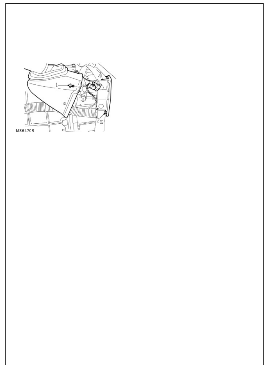
1. Release cover from parking brake lever.
2. Remove 2 bolts and release parking brake lever from body.
3. Release connector from parking brake switch.
4. Remove 2 screws securing parking brake switch to parking
brake lever and remove switch.
Installation
1. Install parking brake switch to parking brake lever and
tighten screws.
2. Install connector to parking brake switch.
3. Position parking brake lever and tighten bolts to 22 Nm (16
lbf.ft).
4. Position cover to parking brake lever.
Нет комментариевНе стесняйтесь поделиться с нами вашим ценным мнением.
Текст