Defender. Manual — part 30
Installation
1. Position axle under vehicle, supporting left side of axle, and
Instal anti-roll bar links.
For additional information, refer to:
Front Stabilizer Bar Link
(204-01 Front Suspension, Removal and Installation).
2. Instal propeller shaft. Tighten bolts to 47 Nm (35 lbf.ft).
3. Instal panhard rod to axle bracket. Tighten bolts to 88 Nm
(65 lbf.ft).
4. Instal drag link to swivel pin arm. Tighten fixings to 40 Nm
(30 lbf.ft).
5. Instal shock absorbers to axle.
6. Instal brake calipers. Tighten bolts to 82 Nm (60 lbf.ft).
7. Tighten upper swivel pin bolts to 78 Nm (58 lbf.ft).
8. Instal radius arms to axle brackets. Tighten bolts to 197 Nm
(145 lbf.ft).
9. Instal steering damper to track rod.
10. Instal radius arms to chassis side member. Tighten fixings
to 197 Nm (145 lbf.ft).
11. Tighten track rod end to 40 Nm (30 lbf.ft) and Instal new
split pin.
12. Remove chassis supports, Instal road wheels and tighten to
correct torque:
1. Alloy wheels - 130 Nm (96 lbf.ft)
2. Steel wheels - 100 Nm (80 lbf.ft)
3. Heavy duty wheels - 170 Nm (125 lbf.ft)
Front Drive Axle/Differential - Differential Carrier
Removal and Installation
Special Tool(s)
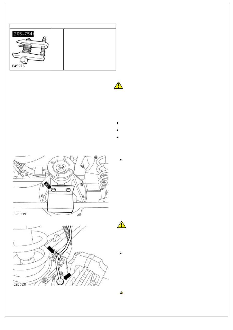
Ball joint separator
205-754 (LRT-54-027)
Removal
1.
CAUTION: Do not work on or under a vehicle supported
only by a jack. Always support the vehicle on safety stands.
Raise and support the vehicle.
2. NOTE: Clean the area around the front axle assembly filler
plug and the front axle assembly drain plug.
Drain the front axle assembly.
Position a container to collect the fluid.
Remove the filler plug.
Remove the drain plug.
3. Remove the front wheels and tires.
4. Remove the tie rod protector.
Remove the 2 bolts.
5.
CAUTION: Before disconnecting or removing
components, make sure the immediate area around joint
faces and connections are clean. Plug open connections to
prevent contamination.
Release the LH front wheel speed sensor.
Release the harness from the clip.
CAUTION: Before disconnecting or removing
6.
CAUTION: Before disconnecting or removing
components, make sure the immediate area around joint
faces and connections are clean. Plug open connections to
prevent contamination.
Disconnect the LH front brake pipe.
Clamp the brake hose to prevent fluid loss.
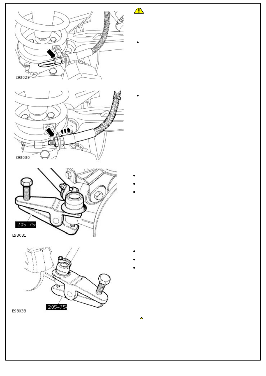
7. Release the LH front brake hose.
Remove the nut.
8. Using the special tool, release the drag link end.
Remove and discard the split pin.
Remove the nut.
Collect the washer.
9. Using the special tool, release the LH tie rod end.
Remove and discard the split pin.
Remove the nut.
Collect the washer.
CAUTION: Do not allow the swivel pin housing to
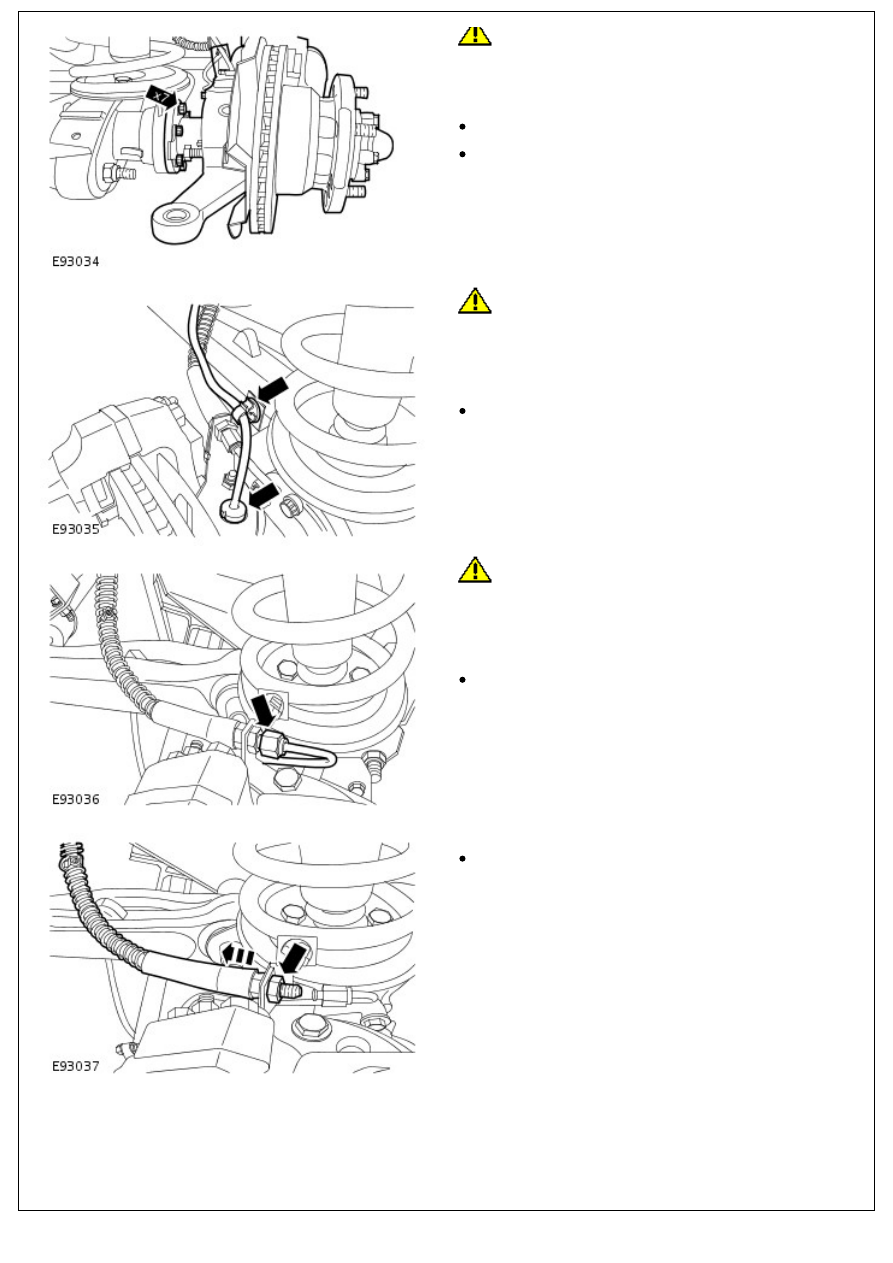
10.
CAUTION: Do not allow the swivel pin housing to
hang on the halfshaft, failure to follow this instruction may
result in damage to the vehicle.
With assistance, remove the LH swivel pin housing.
Remove the 7 bolts.
Remove and discard the gasket.
11.
CAUTION: Before disconnecting or removing
components, make sure the immediate area around joint
faces and connections are clean. Plug open connections to
prevent contamination.
Release the RH front wheel speed sensor.
Release the harness from the clip.
12.
CAUTION: Before disconnecting or removing
components, make sure the immediate area around joint
faces and connections are clean. Plug open connections to
prevent contamination.
Disconnect the RH front brake pipe.
Clamp the brake hose to prevent fluid loss.
13. Release the RH front brake hose.
Remove the nut.
14. Using the special tool, release the RH tie rod end.
Нет комментариевНе стесняйтесь поделиться с нами вашим ценным мнением.
Текст