Defender. Manual — part 59
4. Adjust ball pin centres to nominal length of 924 mm, this
length is adjusted during refit.
5. Centralise steering box.
For additional information, refer to:
Steering Gear
Centralization
(211-00 Steering System - General
Information, General Procedures).
6. Align steering wheel, if necessary.
7.
CAUTION: A sector shaft arm drag link that is damaged
or bent must be renewed. DO NOT attempt repair.
Fit sector shaft arm drag link to swivel housing arms and
tighten nuts to 40 Nm (30 lbf/ft). Fit new split pins.
8. Ensure full steering travel is obtained between lock stops.
For additional information, refer to:
Steering Lock Stop
Adjustment
(211-00 Steering System - General Information,
General Procedures).
Adjust sector shaft arm drag link length to suit.
9. Tap ball joints in direction shown so both pins are in same
angular plane.
10. Tighten clamp bolts to 14 Nm (10 lbf/ft).
11. Refit road wheel and remove axle stands or vehicle from
ramp.
12. Road test vehicle.
13.
WARNING: To correct steering wheel deviations
greater than ± 5° remove and reposition steering wheel.
If driving straight ahead and steering wheel is offset by 0° ±
5° in either direction, correct by adjusting sector shaft arm
drag link length.
Steering Linkage - Steering Gear Drop Arm
Removal and Installation
Removal
1. Park vehicle on level surface and chock rear wheels.
2. Raise vehicle and locate axle stands or use a ramp.
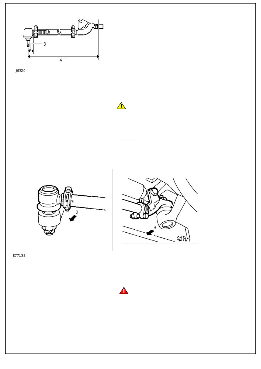
3. Disconnect steering linkage damper from drag link.
For additional information, refer to:
Steering Linkage Damper
(211-03 Steering Linkage, Removal and Installation).
4. Disconnect drag link ball joint from drop arm using
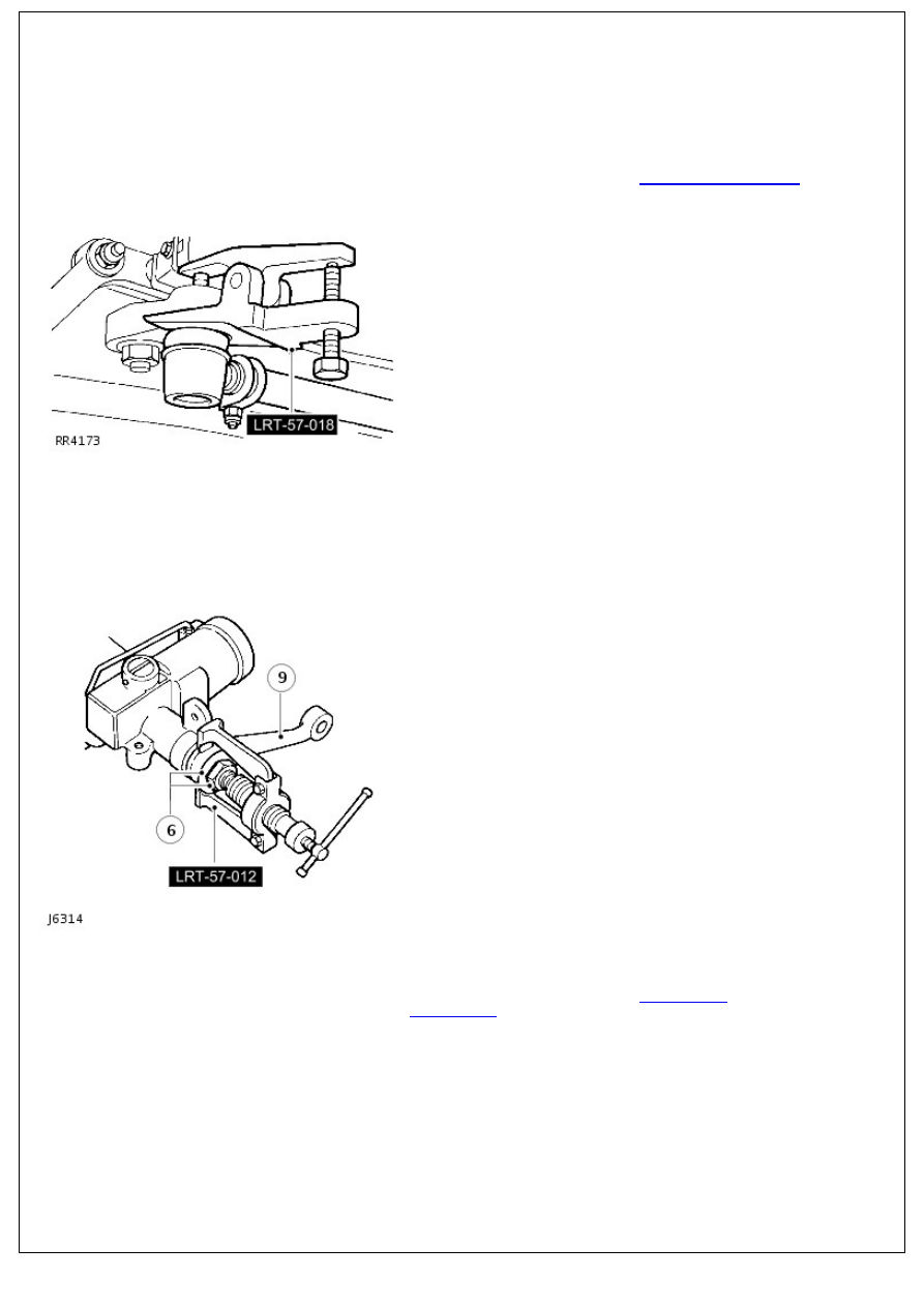
extractor LRT-57-018.
5. Mark drop arm and steering box for reassembly.
6. Bend back tabs on locking washer, slacken retaining nut, but
do not remove.
7. Fit extractor LRT-57-012 and release drop arm from steering
box spline.
8. Remove nut and discard locking washer.
9. Remove drop arm.
Installation
1. Centralise steering box.
For additional information, refer to:
Steering Gear
Centralization
(211-00 Steering System - General
Information, General Procedures).
2. Align reassembly marks and fit drop arm onto steering box
splines.
3. Install new tab washer and retaining nut. Tighten to 176 Nm
(130 lbf.ft) and bend over tab washer.
4. Install drag link to drop arm. Tighten ball joint nut to 40 Nm
(30 lbf.ft).
5. Remove axle stands or vehicle from ramp.
Steering Column - Steering Column
Removal and Installation
Removal
• NOTE: Make sure that the wheels and tires are in the straight-ahead position.
1. Disconnect the battery ground cable.
For additional information, refer to:
Battery Disconnect and
Connect
(414-01 Battery, Mounting and Cables, General
Procedures).
2. Remove the instrument panel.
For additional information, refer to:
Instrument Panel
(501-12
Instrument Panel and Console, Removal and Installation).
3. Remove the steering column lock and ignition switch
housing.
For additional information, refer to:
Steering Column Lock
and Ignition Switch Housing
(211-05 Steering Column
Switches, Removal and Installation).
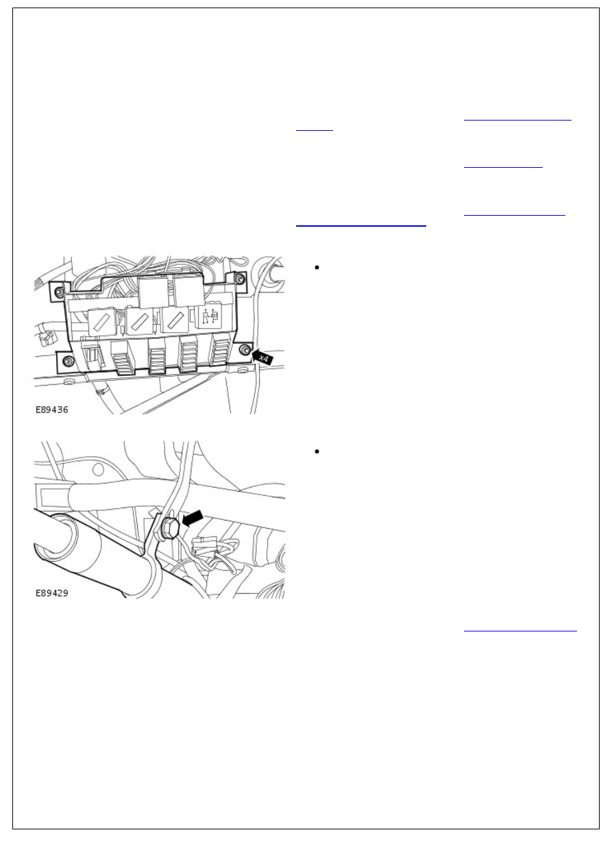
4. Release the central junction box (CJB) from the bulkhead.
Remove the 4 nuts.
5. Release the steering column.
Remove the bolt.
6. Remove the brake pedal and bracket.
For additional information, refer to:
Brake Pedal and Bracket
(206-06 Hydraulic Brake Actuation, Removal and Installation).
7. Release the steering column from the lower shaft.
7. Release the steering column from the lower shaft.
Mark the relationship between both shafts.
Remove and discard the bolt.
8. Release the steering column from the vehicle body.
Remove the 2 bolts.
9. Release the heater control valve and bracket.
Remove the 2 bolts.
10. Remove the steering column upper support bracket.
Remove the 4 bolts.
Collect the rubber strip from around the steering
column shaft.
11. Remove the steering column from the steering column
Нет комментариевНе стесняйтесь поделиться с нами вашим ценным мнением.
Текст