Defender. Manual — part 60
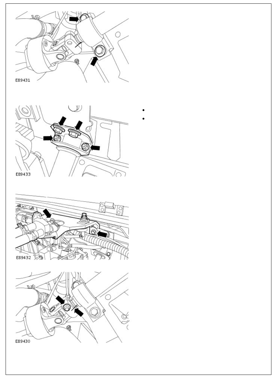
11. Remove the steering column from the steering column
lower shaft.
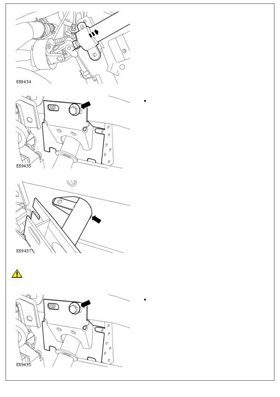
12. Release the steering column main support bracket.
Remove the bolt.
13. NOTE: The steering column must be positioned correctly
to pass through the bulkhead.
Remove the steering column.
Installation
CAUTION: Care must be taken when installing the steering column to the steering column lower shaft, failure to
follow this instruction may result in damage to the steering column lower shaft.
1. To install, reverse the removal procedure.
Tighten to 22 Nm (16 lb.ft).
2. Tighten to 22 Nm (16 lb.ft).
2. Tighten to 22 Nm (16 lb.ft).
3. Install the steering column upper support bracket.
Tighten the M6 bolts to 9 Nm (7 lb.ft).
Tighten the M8 bolts to 22 Nm (16 lb.ft).
4. Tighten to 22 Nm (16 lb.ft).
5. NOTE: Install a new bolt.
Tighten to 30 Nm (22 lb.ft).
6. Tighten to 48 Nm (35 lb.ft).
6. Tighten to 48 Nm (35 lb.ft).
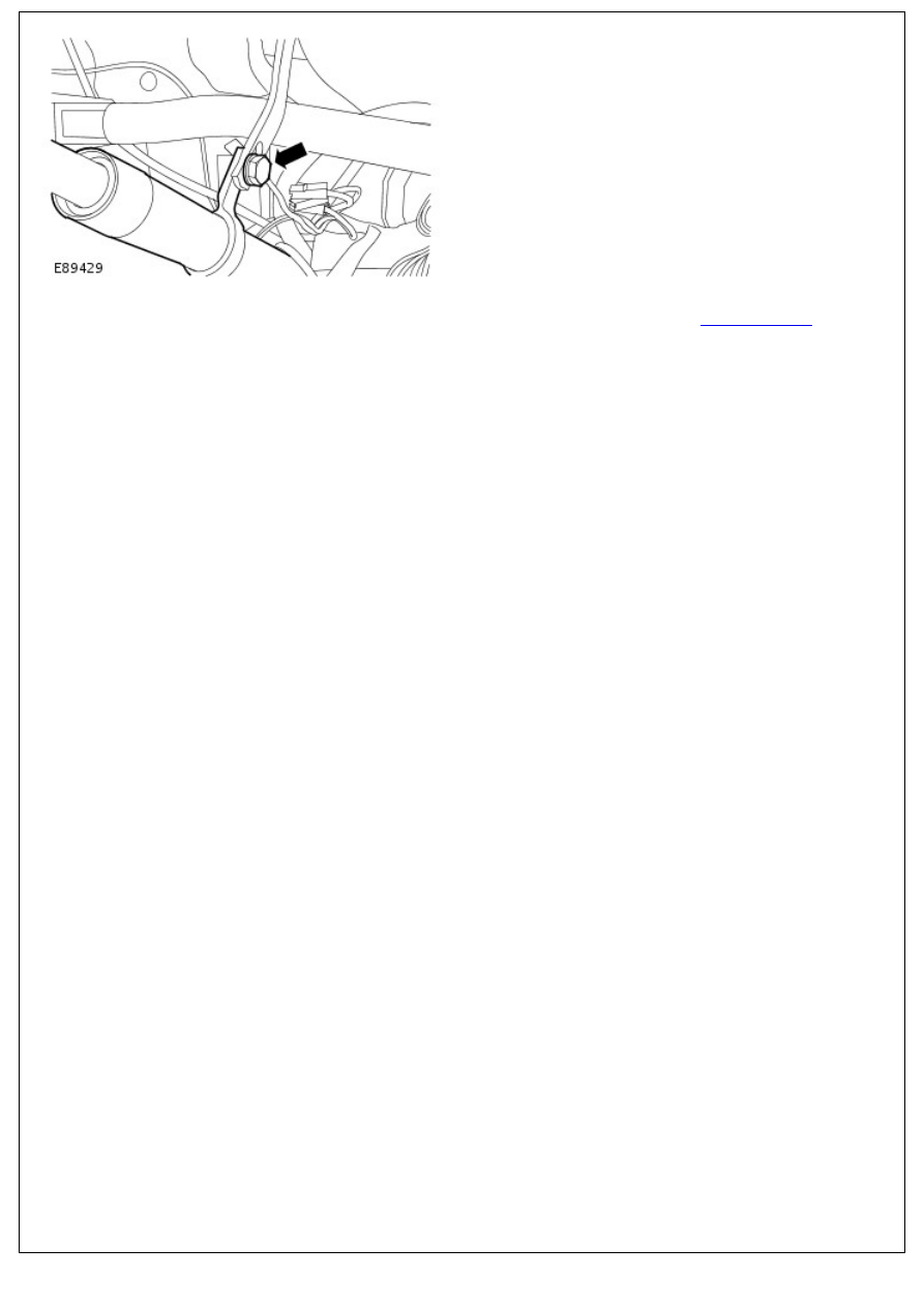
7. Connect the battery ground cable.
For additional information, refer to:
Battery Connect
(414-01
Battery, Mounting and Cables, General Procedures).
Steering Column - Steering Column Lower Shaft
Removal and Installation
Removal
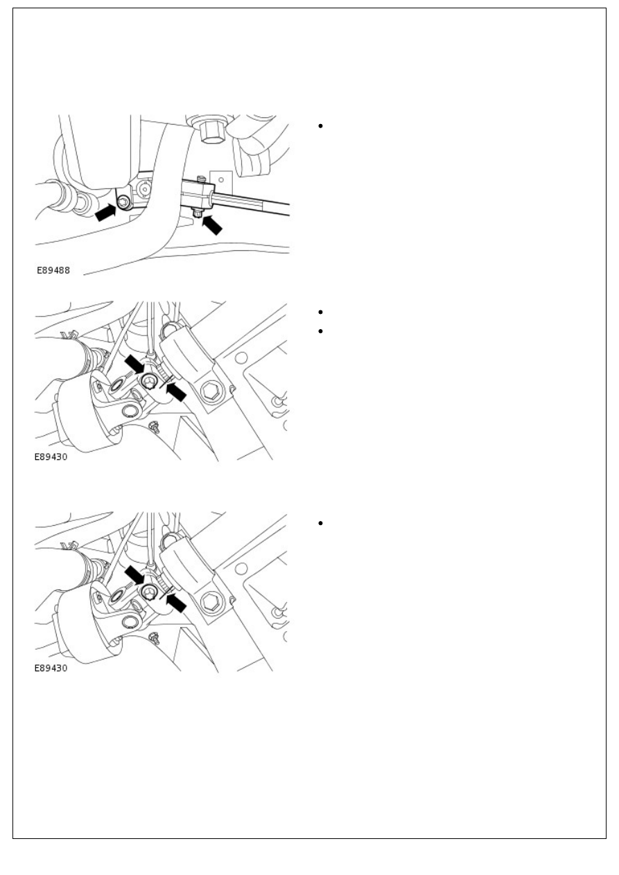
• NOTE: Make sure that the wheels and tires are in the straight-ahead position.
1. Release the steering column lower shaft.
Remove and discard the 2 bolts.
2. Remove the steering column lower shaft.
Mark the relationship between both shafts.
Remove and discard the bolt.
Installation
1. To install, reverse the removal procedure.
Tighten to 30 Nm (22 lb.ft).
2. Tighten to 30 Nm (22 lb.ft).
Нет комментариевНе стесняйтесь поделиться с нами вашим ценным мнением.
Текст