Defender. Manual — part 154
Manual Transmission/Transaxle and Clutch - General Information - Clutch
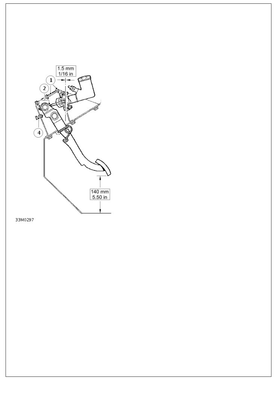
Pedal Freeplay Adjustment
General Procedures
1. Remove 6 screws and detach pedal box top cover and
gasket.
2. Slacken both locknuts on master cylinder push-rod.
3. Check distance from lower edge of clutch pedal to floor.
Correct measurement is 140 mm (5.50 in) without floor
mat.
4. Adjust pedal stop as necessary to obtain correct setting.
5. Adjust master cylinder push rod to obtain approximately 1.5
mm (1/16 in) free play between push-rod and master
cylinder piston.
6. Tighten push rod locknuts.
7. Check operation of clutch pedal and ensure that there is a
minimum of 6 mm (0.25 in) of free play before pressure is
felt. if necessary, readjust master cylinder push-rod.
8. Fit top cover and gasket to pedal bracket.
9. On RH drive vehicles, refit air cleaner.
Clutch - 2.4L Duratorq-TDCi HPCR (103kW/140PS) - Puma -
Description
Nm
lb-ft
Clutch pressure plate bolts (new bolts must be installed)
29
21
Clutch - 2.4L Duratorq-TDCi HPCR (103kW/140PS) - Puma - ClutchVehicles
With: 6-Speed Manual Transmission - MT82
Description and Operation
OVERVIEW
The clutch system is based on the established principle of a single driven plate and diaphragm spring clutch cover
assembly hydraulically actuated from the clutch pedal. Depressing the clutch pedal transfers hydraulic fluid through the
master cylinder, pipe work, and concentric slave cylinder ultimately actuating the clutch fingers to release the clutch and
thus disengage drive from the crankshaft. When your foot is off the pedal, the spring pushes the pressure plate against
the clutch disc, which in turn presses against the flywheel; this locks the engine to the transmission input shaft, causing
them to rotate at the same speed.
The clutch system is of conventional design comprising the following major components:
Clutch master cylinder and pressure pipes
Concentric slave cylinder outlet assembly and peak torque limiter
Vibration damper (Left hand drive vehicles only)
Concentric slave cylinder
Clutch cover assembly
Clutch driven plate
Flywheel
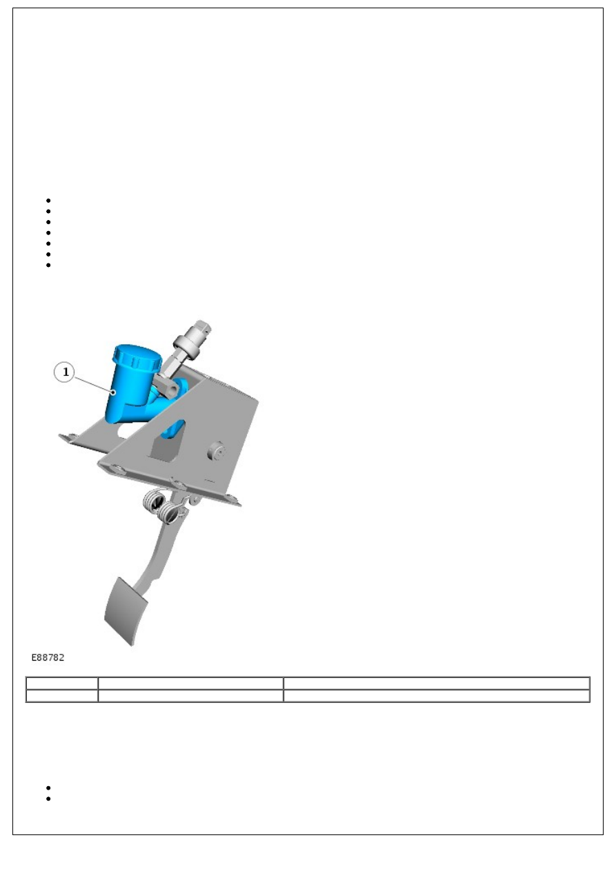
CLUTCH MASTER CYLINDER
Item
Part Number
Description
1
-
Clutch master cylinder
The clutch master cylinder is attached directly to the pedal box assembly, located in the driver's footwell.
The cylinder contains a piston assembly, with a push rod connected to the clutch pedal and spring. When the clutch
pedal is depressed, it pushes on the piston, via a linkage. Pressure builds in the cylinder and lines as the clutch pedal is
depressed further.
The cylinder has 2 hydraulic connections:
A low pressure feed pipe (providing fluid supply from the brake fluid reservoir)
A high pressure pipe
The pedal travel is constrained by an 'up-stop' contained within the master cylinder and a 'down-stop' contained within
the pedal box.
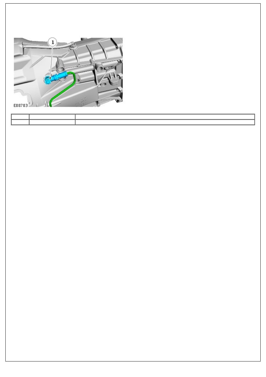
CONCENTRIC SLAVE CYLINDER OUTLET ASSEMBLY
• NOTE: Right hand drive vehicle shown.
Item
Part Number
Description
1
-
Slave cylinder outlet assembly and peak torque limiter
The concentric slave cylinder outlet assembly connects the external pipes with the release system contained within the
clutch housing. A securing bracket locates the assembly in the correct orientation and a seal is provided between the
assembly and the clutch housing.
Contained within the slave cylinder outlet assembly is a peak torque limiter. This component is designed to restrict the
hydraulic fluid flow during the clutch pedal up-stroke. Under normal pedal actuation this restriction can not be detected,
but in the event of an unintentional pedal release (e.g. wet shoe slipping off the clutch pedal) the peak torque limiter
limits the fluid return rate and protects the transmission and driveline form excessive shock loads, which might cause
damage.
On left hand drive vehicles, the hydraulic pipework contains an anti-vibration damper plugged into the peak torque
limiter. This is used to reduce pedal roar/vibrations during clutch operation.
CONCENTRIC SLAVE CYLINDER
The concentric slave cylinder assembly contains the release bearing and the hydraulic slave cylinder. The assembly is
attached to the front end of the transmission via 3 bolts. These bolts are asymmetrically positioned to ensure correct
angular location of the slave cylinder, which is also spigot-mounted for positional fit. In its free condition the slave
cylinder is fully extended, but it positions itself automatically as the clutch housing is fitted to the engine. The assembly
requires no setting or adjustment.
CLUTCH COVER ASSEMBLY
The clutch cover assembly comprises a pressure plate, cover and diaphragm and is mounted on and rotates with the
flywheel.
The pressure plate is machined to provide a smooth surface for the drive plate to engage on. Lugs on the outer
diameter of the pressure plate connect it via leaf springs to the cover. The leaf springs have leaves, which assist in
pulling the pressure plate away from the drive plate when the clutch pedal is depressed.
The cover houses all pressure plate components. Shouldered rivets support the diaphragm inside the cover. The rivets
heads are chamfered to allow the diaphragm to pivot when pressure is applied to it by the release bearing. Holes in the
cover locate on dowels on the flywheel and further holes provide for the attachment of the cover to the flywheel. Larger
holes in the cover provide ventilation for the drive plate and pressure plate and flywheel contact surfaces.
The diaphragm comprises a cast ring with fingers. The diaphragm is attached to the cover with shouldered rivets. The
inner head of each rivet is chamfered to allow the diaphragm to pivot when the clutch is depressed or released. When
pressure is applied to the fingers of the diaphragm by the release bearing, the diaphragm pivots on the rivets and
moves away from the pressure plate, releasing the force applied to the pressure plate and allowing the drive plate to
slip between the pressure plate and the flywheel.
CLUTCH DRIVEN PLATE
The clutch driven plate is sandwiched between the flywheel and the pressure plate of the clutch cover assembly. The
clutch driven plate has a splined hub, which engages with the splines on the primary shaft from the transmission. The
splined hub is located in an inner plate, which contains 3 compression pre-damper springs. The inner plate is retained
by the springs, which can compress in both directions to cushion engine vibration at idle speed. The inner plate is
located on 4 larger compression springs, which are located in a central plate. The hub is sandwiched between the central
plate and the friction damper. The friction damper comprises friction washers located between the hub and the central
plate. The friction washers reduce transmission noises and vibrations due to engine cyclic excitation.
Нет комментариевНе стесняйтесь поделиться с нами вашим ценным мнением.
Текст