Defender. Manual — part 272
Handles, Locks, Latches and Entry Systems - Taildoor Lock Cylinder
Removal and Installation
Removal
1. Remove the taildoor trim panel.
For additional information, refer to:
Taildoor Trim Panel
(501-
05 Interior Trim and Ornamentation, Removal and
Installation).
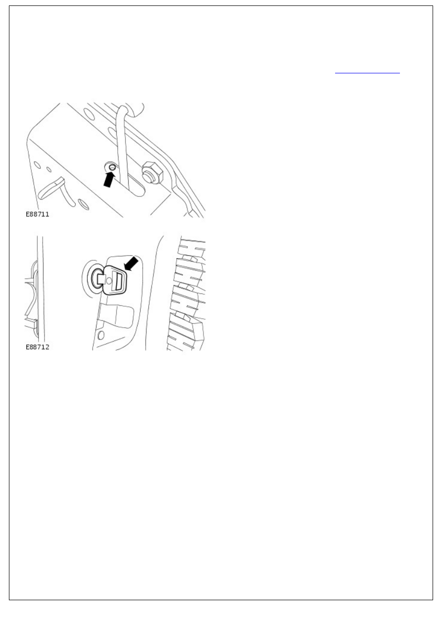
2. NOTE: Make sure the latch is in the locked position.
Using a suitable tool release the lock cylinder.
3. Insert the key and remove the lock cylinder.
Installation
1. To install, reverse the removal procedure.
Handles, Locks, Latches and Entry Systems - Taildoor Lock Motor
Removal and Installation
Removal
1. Remove tail door trim panel.
For additional information, refer to:
Taildoor Trim Panel
(501-
05 Interior Trim and Ornamentation, Removal and
Installation).
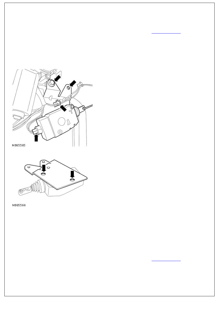
2. Disconnect multiplug from taildoor lock motor.
3. Remove bolt and screw securing taildoor lock motor to
taildoor.
4. Release clip securing harness to taildoor lock motor
mounting bracket.
5. Remove taildoor lock motor assembly from operating rod.
6. Remove 2 screws securing taildoor lock motor to mounting
bracket.
Installation
1. Install taildoor lock motor to mounting bracket and secure
with screws.
2. Connect operating rod to taildoor lock motor.
3. Install taildoor lock motor to door, fit screw and tighten bolt
to 6 Nm (4 lbf.ft).
4. Position harness to taildoor lock motor mounting bracket and
secure with clip.
5. Connect multiplug to taildoor lock motor.
6. Install taildoor trim panel.
For additional information, refer to:
Taildoor Trim Panel
(501-
05 Interior Trim and Ornamentation, Removal and
Installation).
Wipers and Washers - Wipers and Washers
Description and Operation
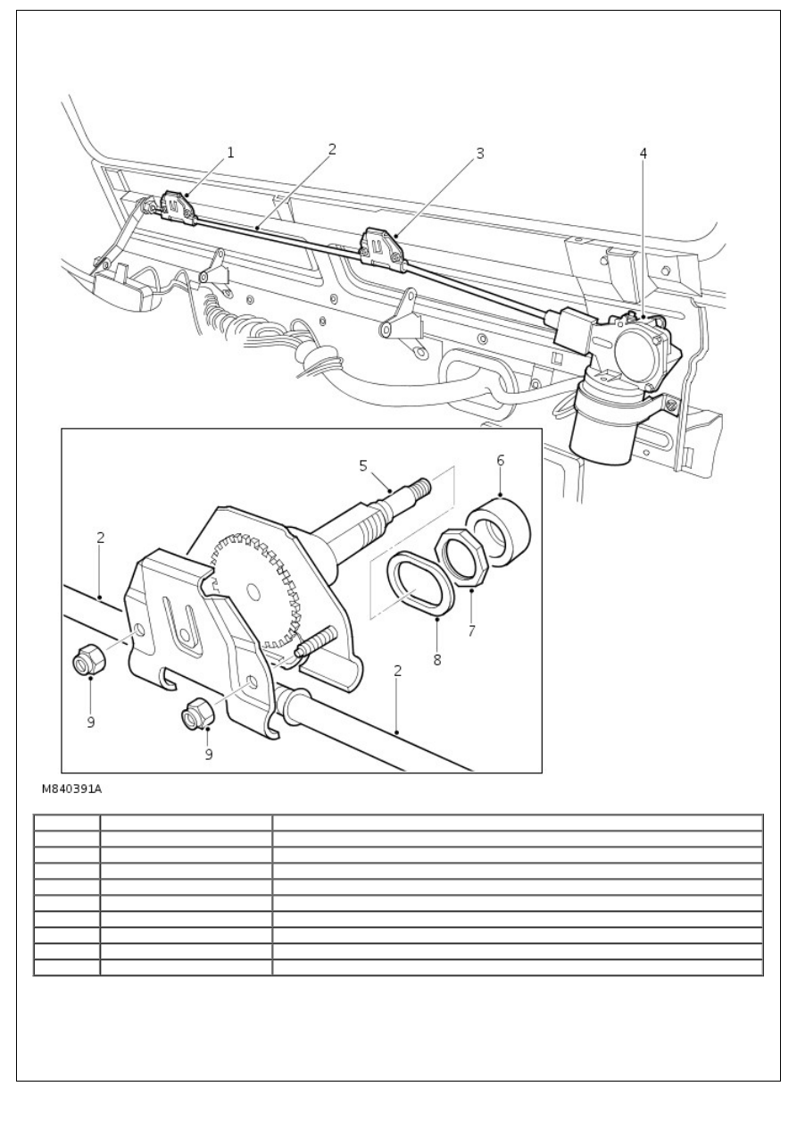
Item
Part Number
Description
1.
-
LH wheelbox
2.
-
Cable
3.
-
RH wheelbox
4.
-
Wiper motor
5.
-
Spindle with DIN taper arm attachment
6.
-
Spacer
7.
-
Locknut
8.
-
Seal
9.
-
Locknuts
WINDSCREEN WIPERS
Although windscreen wiper functionality remains the same, the mechanical architecture has undergone significant
changes, for 2002 Model year. The body structure has undergone some minor changes to house the revised wiper
linkage.
A modified wiper motor is introduced which is balanced to reduce operation noise. The brush plate is fitted with
capacitors to reduce radio interference and a thermal cut-out is introduced to prevent motor burnout. The motor also
contains a new park switch which also reduces operation noise. A common motor is now used on both LHD and RHD
variants.
The motor is repositioned on the bulkhead which allows a straighter drive cable run. The straighter run reduces load on
the cable allowing a stiffer cable to be used. The stiffer cable and the incorporation of a reduced friction material
reduces torsion wind-up of the cable and results in smoother wiper operation and a reduction of blade over travel.
New, larger wheel boxes are fitted in an inverted position from the previous installation. The bulkhead mounting holes
are larger with flats for positive location of the wheel box spindle. The wheel boxes now feature a 40 tooth gear ratio in
lieu of a 32 tooth gear. This reduces backlash and load and further reduces blade over travel. The wheel box casings
are secured with locknuts.
The wheel box spindles now have a splined DIN taper fitting for the new wiper arms which are secured on the spindle
with an M8 nut. The taper improves arm retention.
A new grease is introduced which improves wiper operation at very low temperatures.
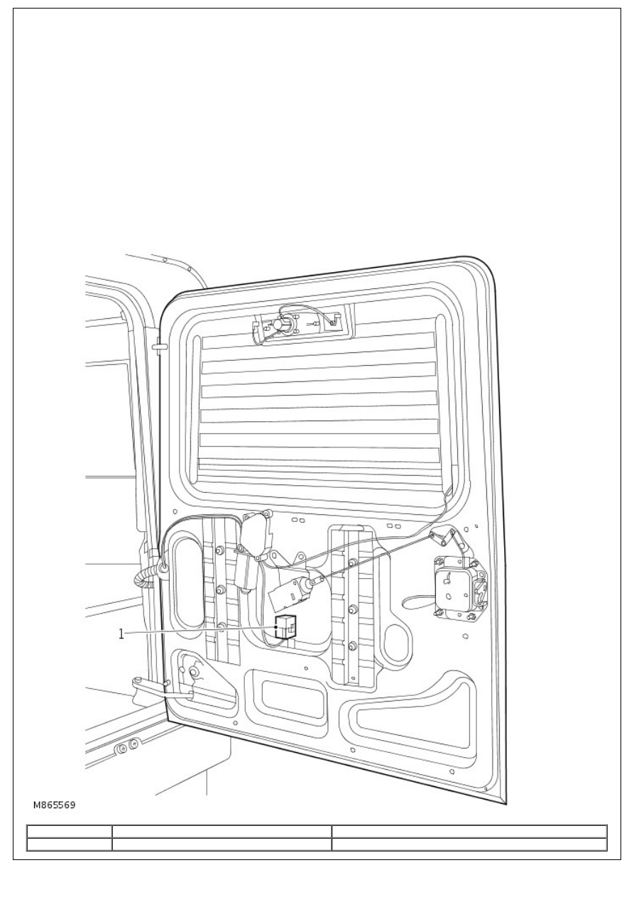
REAR WIPER
Item
Part Number
Description
1.
-
Rear wiper relay
Нет комментариевНе стесняйтесь поделиться с нами вашим ценным мнением.
Текст