Defender. Manual — part 32
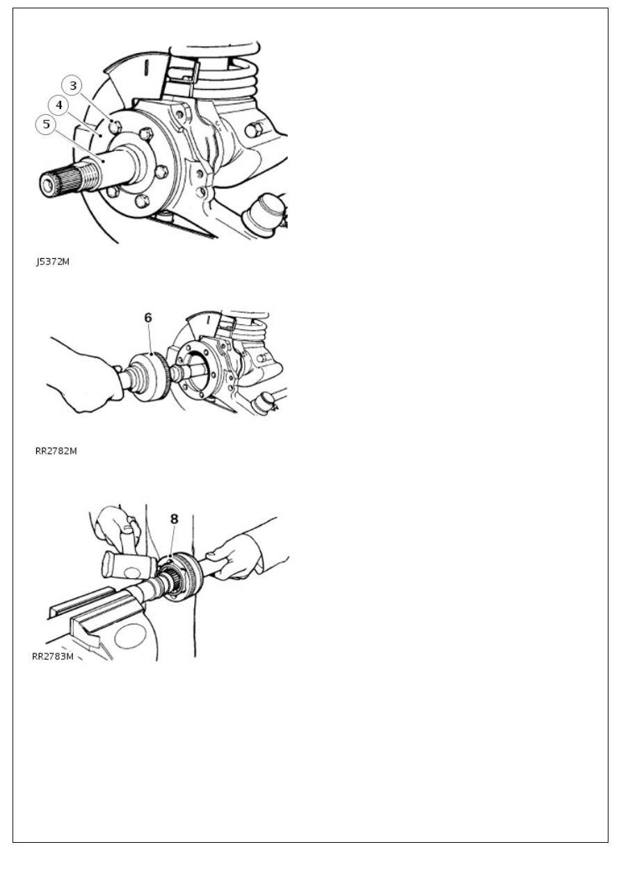
5. Remove stub axle and joint washer.
6. Withdraw axle shaft and constant velocity joint from axle
casing.
7. Hold axle shaft firmly in a soft jawed vice.
8. Using a soft mallet drive constant velocity joint from shaft.
9. Remove circlip and collar from axle shaft.
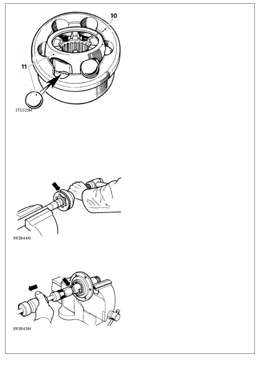
10. Mark positions of constant velocity joint, inner and outer
race and cage for reassembly.
11. Swivel cage and inner race to remove balls.
11. Swivel cage and inner race to remove balls.
12. Examine all components, in particular, inner and outer
track, cage balls and bearing surfaces for damage and
excessive wear.
13. Maximum acceptable end-float on assembled joint 0,64mm.
Renew if worn or damaged. Lubricate with a recommended oil
during assembly.
Assembly
1. Install collar and a new circlip.
2. Engage constant velocity joint on axle shaft splines and
using a soft mallet, drive joint in fully.
3. Drill and chisel off thrust ring taking care to avoid damaging
stub axle.
4. Remove bearing and oil seal using special tool LRT-37-004
and slide hammer LRT-99-004. Ensure lip of tool locates
behind bearing to drive it out.
5. Repeat instruction for removal of oil seal.
6. Lubricate seal and lip with EP90 oil and with cavity side
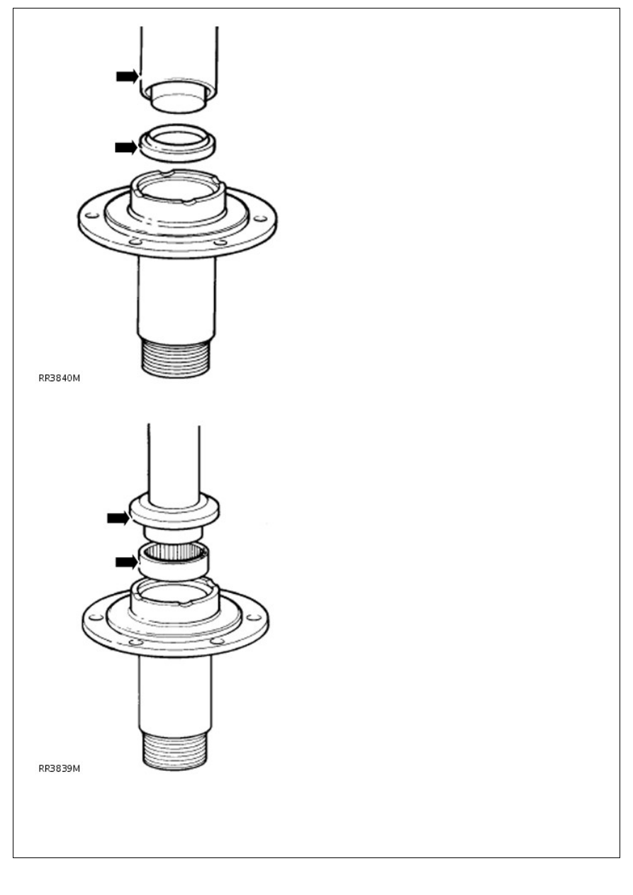
leading press in a new oil seal using special tool LRT-54-
004.
7. Using special tool LRT-54-005, fit bearing with its part
number visible when fitted, and flush with end face of stub
axle.
8. Press fit a new thrust ring onto stub axle.
9. NOTE: Removal of oil seal and retaining plate is achieved
when swivel bearing housing is removed.
Remove bolts securing oil seal retaining plate and joint
washer. Release assembly from swivel pin housing.
10. Remove 2 bolts, retaining lower swivel pin to housing.
11. Remove brake disc shield bracket.
12. Tap lug to remove lower swivel pin and joint washer.
13. Remove two bolts retaining brake hose bracket and top
swivel pin.
14. Remove bracket, top swivel pin and shims.
15. Remove swivel pin housing while retrieving lower and upper
bearings.
16. NOTE: Use upper bearing opening to gain access to lower
bearing track.
Remove lower bearing track from swivel bearing housing.
17. Remove 7 bolts retaining swivel bearing housing to axle
case.
18. Remove inner oil seal from back of housing.
19. NOTE: Use lower bearing opening to gain access to upper
bearing track.
Remove top bearing track from swivel bearing housing.
20. If worn, pitted or damaged, renew housing.
21.
CAUTION: Ensure bearing tracks are fitted square or
damage could occur.
Install upper and lower bearing tracks into swivel bearing
housing.
22. With seal lips trailing, install swivel housing inner oil seal
into rear of housing. Grease seal lips.
23. Coat swivel bearing housing to axle casing bolts with
sealant, Part No. STC 50552.
24. Coat both sides of joint washer with a sealing compound.
Position swivel bearing housing to axle mating face.
25. Place retaining plate, joint washer and oil seal over axle
flange ready for assembly.
26. Install swivel bearing housing to axle flange with 7 bolts.
Tighten to 73 Nm (54 lbf.ft).
27. Grease and install upper and lower swivel pin taper roller
bearings.
28. Position swivel pin housing over swivel bearing housing.
29. Coat joint washer both sides with sealing compound and
position on lower swivel pin.
30. Loosely install brake shield bracket plus lower swivel pin
with lug outboard to swivel pin housing.
31. Loosely install top swivel pin plus existing shims and brake
hose bracket to swivel pin housing.
32. Apply sealant, Part No. STC 50552 to threads of lower
swivel pin bolts; tighten bolts to 25 Nm (18 lbf.ft), bend over
lock tabs.
33. Apply sealant Part No. STC 50552 to threads of top swivel
pin bolts, install bolts and tighten to 65 Nm (48 lbf.ft).
34. NOTE: Swivel housing oil seal and axle should not be
Нет комментариевНе стесняйтесь поделиться с нами вашим ценным мнением.
Текст