Defender. Manual — part 238
Module Communications Network - Communications Network
Description and Operation
OVERVIEW
A high speed controller area network (CAN) bus is used to transfer data between the engine control module (ECM) and
instrument cluster.
The diagnostic socket is also connected to the high speed CAN bus and allows the Land Rover approved diagnostic
system to interrogate both the ECM and instrument cluster software.
The CAN bus is a high speed broadcast network where control modules automatically transmit information every few
microseconds. Information is broadcast down a pair of twisted wires, known as 'CAN high' and 'CAN low'. Information is
transmitted on the CAN bus as a voltage difference between the 2 wires.
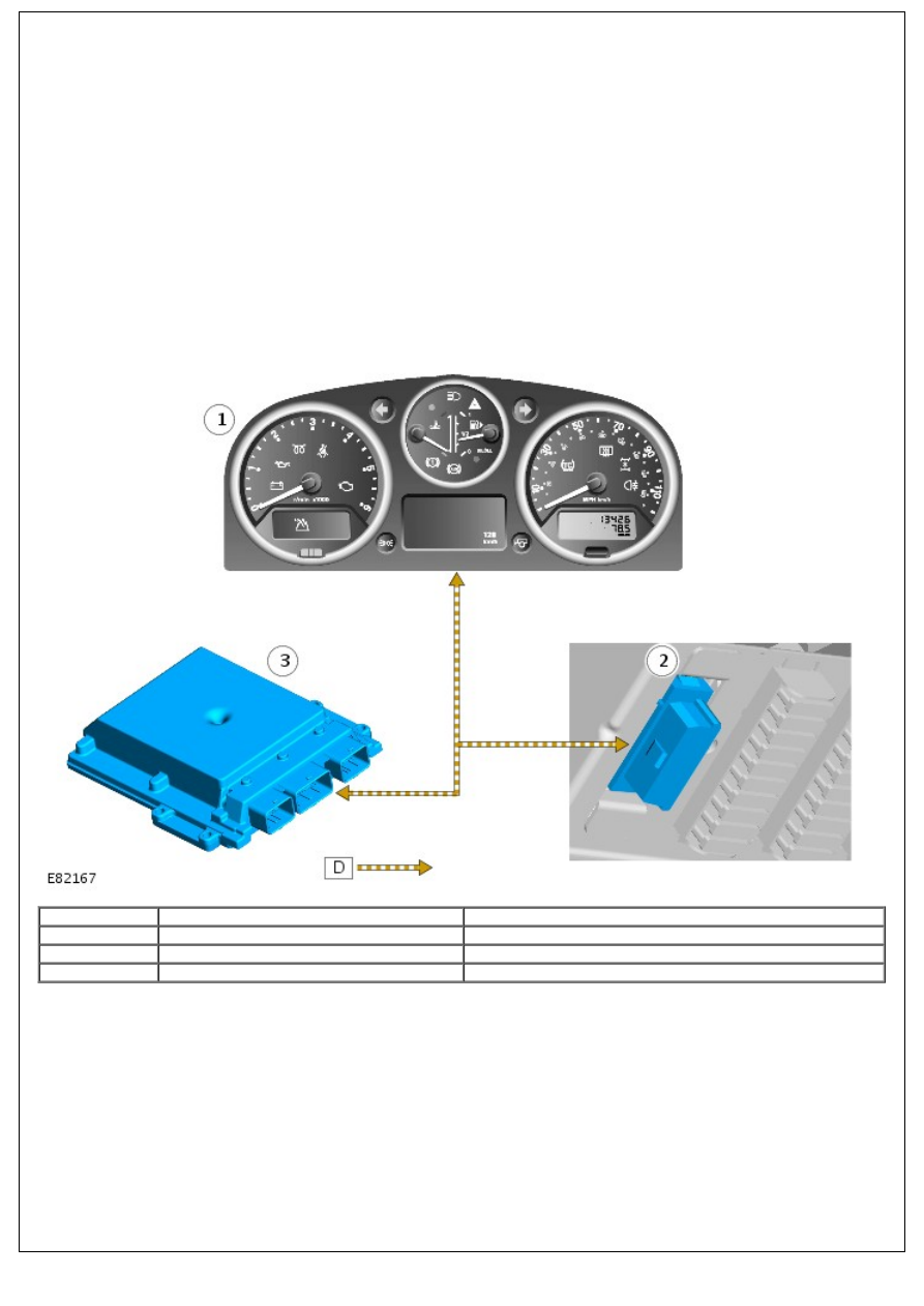
CONTROL DIAGRAM
• NOTE: D = High speed CAN bus
Item
Part Number
Description
1
-
Instrument cluster
2
-
Diagnostic socket
3
-
ECM
Anti-Theft - Active - Anti-Theft - Active
Description and Operation
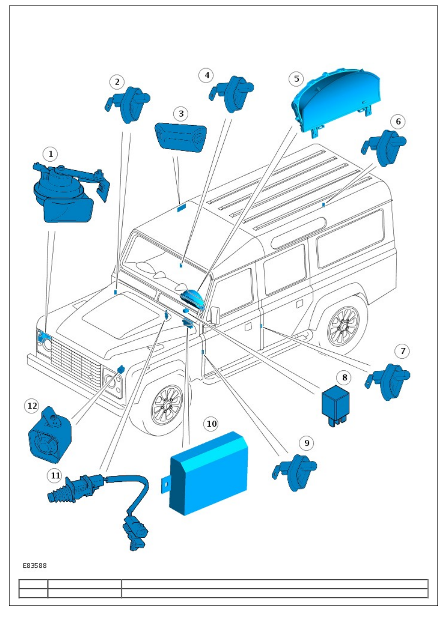
COMPONENT LOCATION
Item
Part Number
Description
1
-
Anti-theft alarm horn (if fitted)
2
-
right-hand (RH) front door switch
3
-
Intrusion detection module (90/110 station wagon shown)
4
-
RH rear door switch (if fitted)
5
-
Instrument cluster
6
-
Tail door switch
7
-
left-hand (LH) rear door switch (if fitted)
8
-
Anti-theft alarm horn relay (if fitted)
9
-
LH front door switch
10
-
Anti-theft system module
11
-
Hood switch
12
-
Battery backed sounder (if fitted)
OVERVIEW
The 10AS anti-theft system monitors the hinged panels for unauthorized opening. The system also monitors intrusion
within the cabin. Depending on market specification, the vehicle may be fitted with either a battery backed sounder or
an anti-theft alarm horn.
The controlling software for the active anti-theft system is contained within the anti-theft system module. The anti-theft
system module also controls;
the passive anti-theft system (engine immobilization).
For additional information, refer to:
Anti-Theft - Passive
(419-01B Anti-Theft - Passive, Description and
Operation).
the central locking system.
For additional information, refer to:
Handles, Locks, Latches and Entry Systems
(501-14 Handles, Locks, Latches
and Entry Systems, Description and Operation).
interior lighting.
For additional information, refer to:
Interior Lighting
(417-02 Interior Lighting, Description and Operation).
the hazard flashers.
For additional information, refer to:
Exterior Lighting
(417-01 Exterior Lighting, Description and Operation).
The active anti-theft system is armed by pressing the lock button on the remote handset or using the vehicle key in the
drivers door lock. Using the remote handset will arm both the perimetric and volumetric anti-theft systems. Using the
vehicle key will only arm the perimetric anti-theft system.
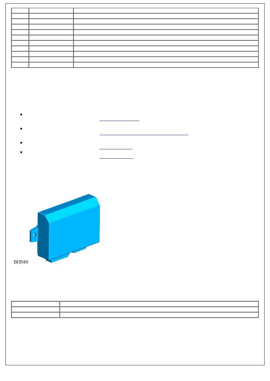
ANTI-THEFT SYSTEM MODULE
The anti-theft system module is located behind the instrument cluster and receives a permanent battery supply from the
battery junction box (BJB). The control module incorporates a radio frequency (RF) receiver and antenna to receive
signals transmitted from the remote handset.
Depending on market specification, the module will operate at one of two frequencies. This is identified by a label
mounted on the module casing. The table below shows the frequencies available for each market.
Frequency
Markets
433 MHz
Europe, Gulf States, South Africa
315 MHz
North America, South East Asia, Japan, Australia
The anti-theft system module also incorporates an internal inertia switch. In the event of an impact of sufficient severity
to trigger the inertia switch when the ignition switch is in position II, the anti-theft system module will unlock all doors
and operate the hazard flashers. The anti-theft system module will remain in this mode of operation for 2 minutes. To
de-activate the hazard flashers and restore the anti-theft system module to its normal mode of operation, the ignition
switch should be turned to position 0 and back to position II after the 2 minute period has expired.
REMOTE HANDSET
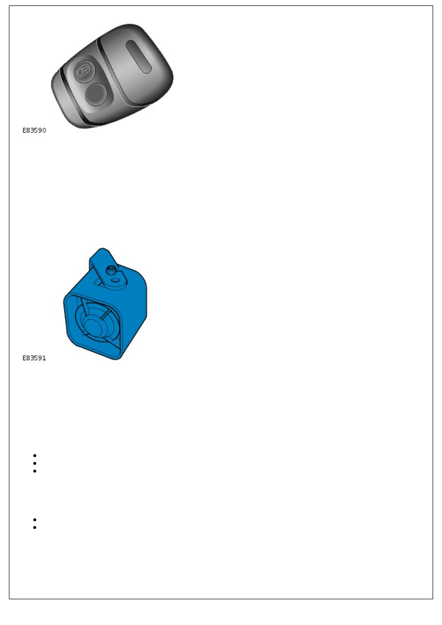
The remote handset is used to arm and disarm the anti-theft alarm system. The handset comprises a lock and unlock
button. Internally, the handset contains a printed circuit board capable of transmitting RF signals, and a battery.
The remote handset RF code comprises 2 parts. The first part is a fixed code that is unique to the handset. The second
part is a rolling code which changes in accordance with a pre-determined pattern. The code is received by the anti-theft
system module, which is able to store information on up to 4 different handsets.
If the remote handset battery falls below a pre-determined level, the handset will transmit an additional RF signal code
to the anti-theft system module. This signal is relayed to the instrument cluster indicator which emits 2 rapid flashes
every 0.5 seconds to inform the driver that the remote handset battery needs replacing.
BATTERY BACKED SOUNDER
Depending on market specification, the vehicle may be fitted with a battery backed sounder. The battery backed
sounder is located in the LH front fender, behind the headlamp. The battery backed sounder is tamper proof and as the
name suggests contains its own power supply. This allows it to operate even if it is disconnected from the vehicle power
supply. For added security all wires leading to and from the battery backed sounder are colored black.
If the battery backed sounder is disconnected without first being disarmed it will sound for 4 minutes 30 seconds, if not
reset in the interim. The alarm cycle in this period will be made up of a 30 second continuous tone, followed by a 5
second silent interval.
To disarm the battery backed sounder, to allow for its disconnection, the following sequence must be carried out:
Turn the ignition switch to position II then back to position 0,
Disconnect the vehicle battery within 17 seconds of switching off the ignition,
Disconnect the battery backed sounder.
If the battery backed sounder is triggered by a battery disconnection it can be reset by turning the starter switch to
position II provided the remote control is on the same key ring as the key, or is in close proximity to the ignition switch.
If the battery backed sounder is triggered by the perimetric or volumetric anti-theft systems, it can be reset by either:
pressing a button on the remote handset, or
by turning the starter switch to position II provided the remote control is on the same key ring as the key, or is
in close proximity to the ignition switch.
ANTI-THEFT ALARM HORN
Нет комментариевНе стесняйтесь поделиться с нами вашим ценным мнением.
Текст