Defender. Manual — part 41
Hydraulic Brake Actuation - Brake Pressure Control Valve
Removal and Installation
Removal
1. Disconnect battery.
2. Clean area around brake pressure control valve ports.
3. Place a container under valve to catch escaping brake fluid.
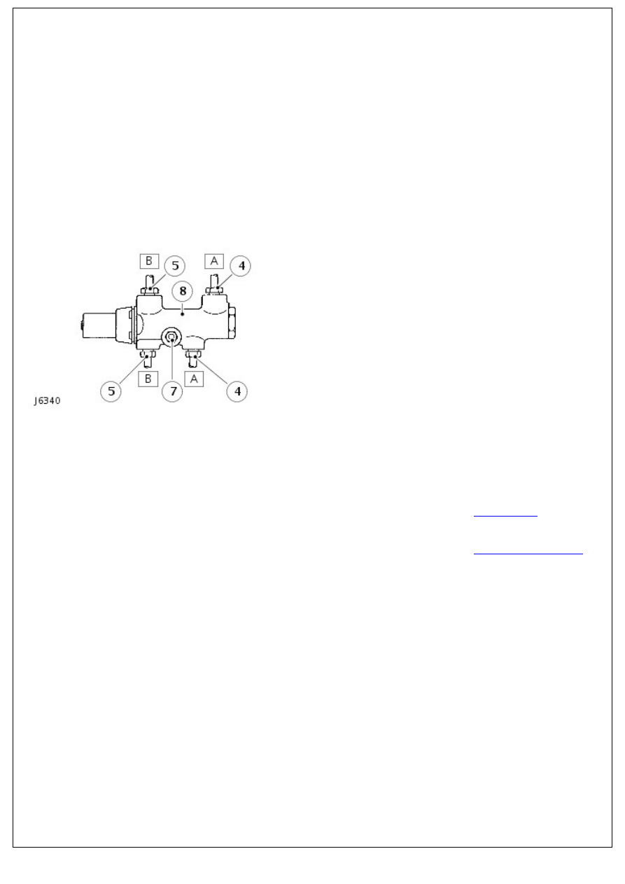
4. Disconnect primary circuit pipe unions 'A' from brake
pressure control valve.
5. Disconnect secondary circuit pipe unions 'B' from brake
pressure control valve.
6. Cover pipes to prevent ingress of dirt.
7. Remove single retaining nut and bolt securing brake
pressure control valve to engine bulkhead.
8. Remove brake pressure control valve.
Installation
1. Fit brake pressure control valve to engine bulkhead. Tighten
bolt to 15 Nm (11 lbf/ft).
2. Connect primary and secondary circuit pipes to brake
pressure control valve. Tighten unions to 16 Nm (12 lbf/ft).
3. Fill brake reservoir with recommended brake fluid.
For additional information, refer to:
Specifications
(206-00
Brake System - General Information, Specifications).
4. Bleed the brake system.
For additional information, refer to:
Brake System Bleeding
(206-00 Brake System - General Information, General
Procedures).
5. Reconnect battery and road test vehicle.
Hydraulic Brake Actuation - Brake Master Cylinder
Disassembly and Assembly
Disassembly
1. Disconnect battery and remove master cylinder from booster.
For additional information, refer to:
Battery Disconnect and
Connect
(414-01 Battery, Mounting and Cables, General
Procedures).
2. Before commencing overhaul procedure thoroughly clean
master cylinder and inspect outer surfaces for damage and
condition, renew complete assembly if necessary.
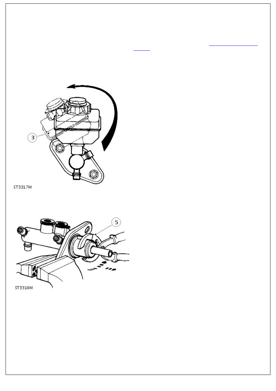
3. The reservoir is a push fit in master cylinder and secured
by seals. Carefully ease reservoir from master cylinder by
rolling it from seals as illustrated.
4. Using soft jaws, one either side of master cylinder flange
and clamp flange in a suitable vice. Remove water ingress O-
ring seal from master cylinder to booster flange and discard.
5. Hold outside of transfer housing with a suitable pair of
grips, carefully pull, while working pliers in a backwards
and forwards rocking motion to ease housing off master
cylinder, discard housing and vacuum seal.
6. Withdraw 2 reservoir seals from master cylinder and note
their positions in inlet ports for reassembly. Discard both
seals.
7. Remove retaining ring and O-ring seal from machined
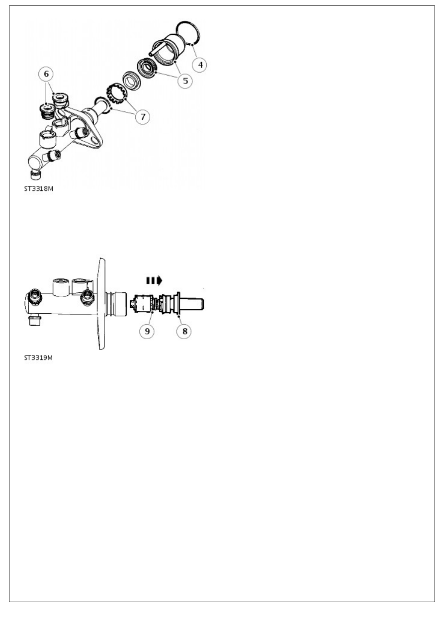
7. Remove retaining ring and O-ring seal from machined
outer surface of master cylinder, discard both seal and
retaining ring.
8. Remove guide ring from mouth of master cylinder which
supports primary plunger assembly and place to one side,
this component is not part of master cylinder service kit and
is to be refitted on assembly of unit.
9. Pull primary plunger assembly out of master cylinder.
• NOTE: The primary plunger assembly cannot be broken down any further and is serviced as a complete unit. Discard
assembly.
10. The secondary plunger assembly will remain at bottom of
master cylinder bore, plunger can be easily expelled by
tapping assembly on a piece of timber until plunger appears
at cylinder mouth, carefully pull plunger from master cylinder.
11. If swirl tube was not expelled at same time as secondary
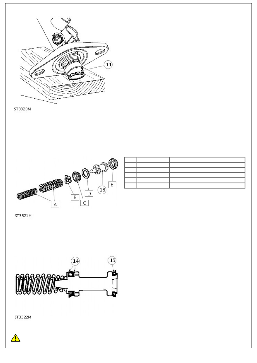
11. If swirl tube was not expelled at same time as secondary
plunger, repeat above operation to expel it from bottom of
master cylinder bore and discard.
12. Clean all parts with Gilling cleaning fluid or unused brake
fluid and place cleaned parts on to a clean sheet of paper.
Inspect cylinder bore and plungers for signs of corrosion,
ridges and score marks. Provided working surfaces are in
perfect condition, new seals from a Gilling Service repair kit
may be used.
13. Remove components above from secondary plunger and
discard:
Item Part Number
Description
A
-
Springs
B
-
Seal retainer
C
-
Recuperating seal (primary cup)
D
-
Washer
E
-
'L' seal
• NOTE: A small screwdriver with end rounded and polished is required to remove 'L' seal. DO NOT damage secondary
plunger.
14. Coat new seals in unused brake fluid and firstly install 'L'
seal to plunger.
15. Install washer followed by recuperating seal. Install seal
retainer and springs, ensure springs are correctly seated.
Assembly
CAUTION: It is important that the following instructions are carried out precisely, otherwise damage could be
Нет комментариевНе стесняйтесь поделиться с нами вашим ценным мнением.
Текст