Defender. Manual — part 204
Climate Control System - General Information - Refrigerant System Tests
General Procedures
1. Place the vehicle in a ventilated, shaded area free from
excessive draught, with the doors and windows open.
2. Check that the surface of the condenser is not restricted with
dirt, leaves, flies, etc. Do not neglect to check the surface
between the condenser and the radiator. Clean as necessary.
3. Switch on the ignition and the air conditioner air flow control.
Check that the blower is operating efficiently at low, medium
and high speeds. Switch off the blower and the ignition.
4. Check that the evaporator drain tube is open and clear.
5. Check the tension of the compressor driving belt, and adjust
if necessary.
6. Inspect all connections for the presence of refrigerant oil. If
oil is evident, check for leaks, and repair as necessary.
• NOTE: The compressor oil is soluble in Refrigerant R134a and is deposited when the refrigerant evaporates from a
leak.
7. Start the engine.
8. Set the temperature controls to cold and switch the air
conditioner blower control on and off several times, checking
that the magnetic clutch on the compressor engages and
releases each time.
9. With the temperature control at maximum cooling and the
blower control at high speed, warm up the engine and fast
idle at 1000 rev/min.
10. Repeat at 1800 rev/min.
11. Gradually increase the engine speed to the high range and
check the sight glass at intervals.
12. Check for frosting on the service valves.
13. Check the high pressure hoses and connections by hand for
varying temperature. Low temperature indicates a restriction
or blockage at that point.
14. Switch off the air conditioning blower and stop the engine.
15. If the air conditioning equipment is still not satisfactory,
carry out a pressure test as previously described in this
section.
Climate Control System - General Information - Electronic Leak Detection
General Procedures
CAUTION: When a major repair has been carried out, a leak test should be carried out using an inert gas (see
below).
1. Place the vehicle in a well ventilated area but free from
draughts, as leakage from the system could be dissipated
without detection.
2. Follow the instructions issued by the manufacturer of the
particular leak detector being used.
3. Commence searching for leaks by passing the detector probe
around all joints and components, refrigerant gas is heavier
than air.
4. Insert the probe into an air outlet of the evaporator or into
the evaporator drain tube. Switch the air conditioning blower
on and off at intervals of ten seconds. Any leaking refrigerant
will be gathered in by the blower and detected.
5. Insert the probe between the magnetic clutch and
compressor to check the shaft seal for leaks.
6. Check all service valve connections, valve plate, head and
base plate joints and back seal plate.
7. Check the condenser for leaks at the pipe unions.
8. If any leaks are found, the system must be discharged
before rectification.
9. Rectify any leaks and recheck for leaks during evacuation
prior to charging.
10. Leak test using inert gas
1. Connect gas line to recharging station.
2. Pressurise system to 3 bar (45 lbf/in!).
3. Carry out leak test as above.
Air Distribution and Filtering - Air Distribution and Filtering
Description and Operation
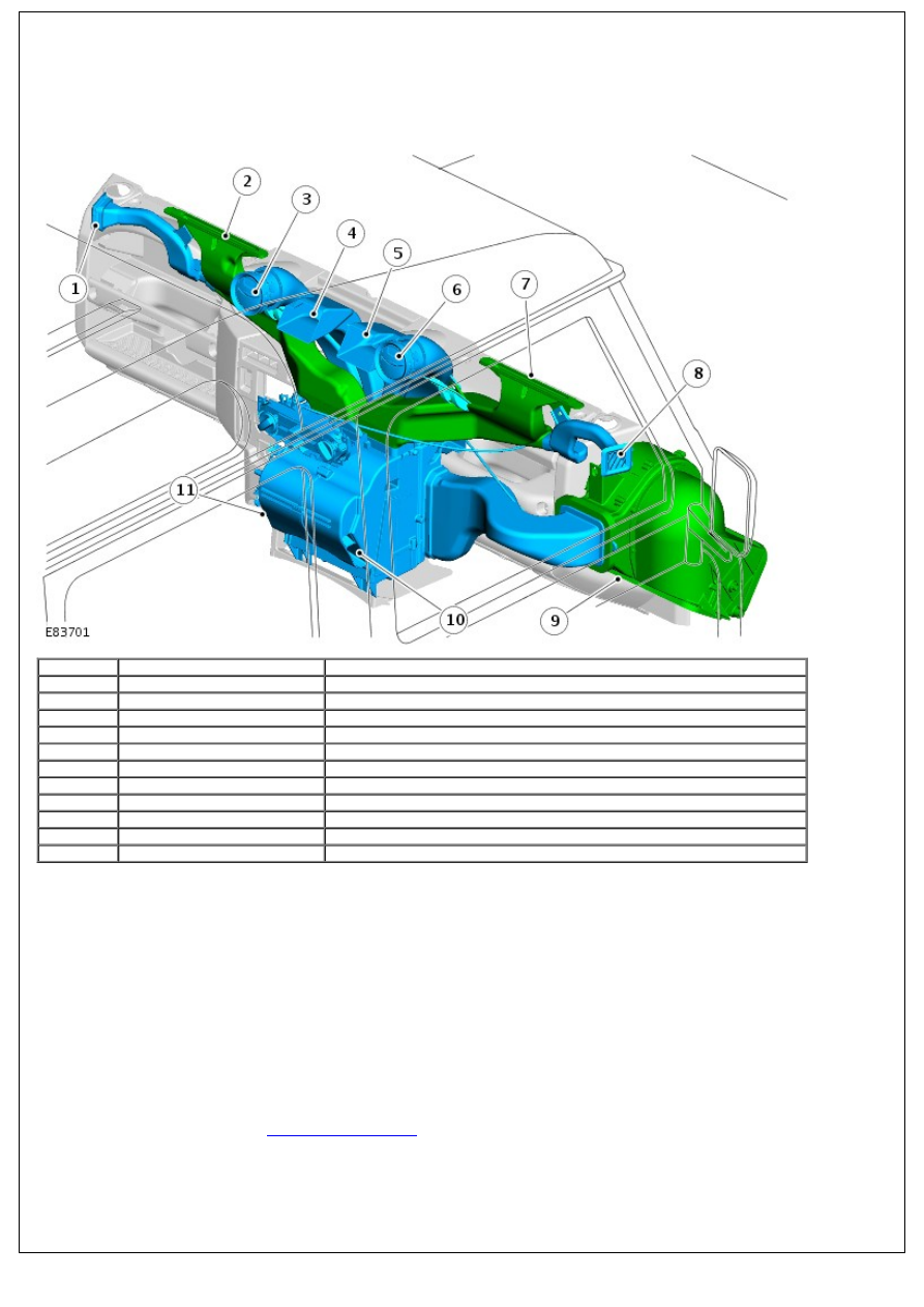
COMPONENT LOCATION
• NOTE: left-hand drive (LHD) vehicle shown, right-hand drive (RHD) similar.
Item
Part Number
Description
1
-
left-hand (LH) side window vent
2
-
Windshield LH vent
3
-
LH face level register
4
-
LH face level vent
5
-
right-hand (RH) face level vent
6
-
RH face level register
7
-
Windshield RH vent
8
-
RH side window vent
9
-
Recirculated air inlet
10
-
RH footwell vent
11
-
LH footwell vent
OVERVIEW
Air intake into the cabin is controlled using a 2 position sliding switch located on the center console. Either fresh or
recirculated air can be selected. Selections are transmitted to the air intake and blower assembly using a Bowden cable.
The air intake and blower assembly is located in the engine compartment.
Fresh air enters the system through the air inlet duct mounted in the passenger side front fender. Inlet air travels
through the air intake and blower assembly to the heater assembly where it is distributed into the front of the cabin via
a series of ducts, registers and vents.
• NOTE: The vehicle is not fitted with a pollen filter.
When selected, recirculated air enters the system through an inlet located in the lower surface of the instrument panel,
above the passenger foot well.
Air distribution into the cabin is selected using the RH rotary control mounted on the center console. A Bowden cable
transmits selections to 2 air distribution doors using cams mounted on the heater assembly.
For additional information, refer to:
Climate Control System
(412-00 Climate Control System - General Information,
Description and Operation).
Air Distribution and Filtering - Air Inlet Duct
Removal and Installation
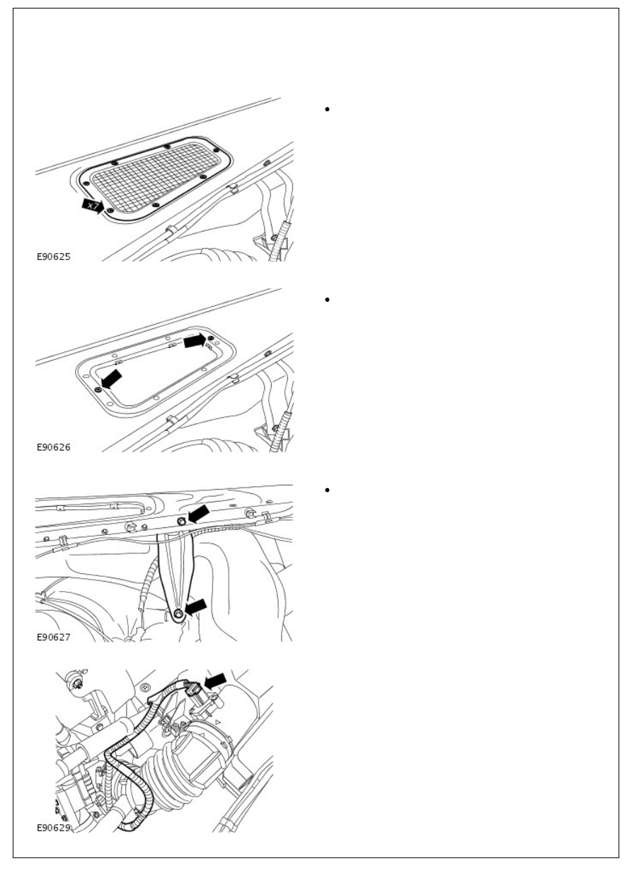
Removal
1. Remove the air inlet grille.
Remove the 7 screws.
2. Release the air inlet duct.
Remove the 2 screws.
3. Remove the fender support bracket.
Remove the 2 bolts.
4. Disconnect the mass air flow (MAF) sensor electrical
connector.
Нет комментариевНе стесняйтесь поделиться с нами вашим ценным мнением.
Текст