Defender. Manual — part 202
Item
Part Number
Description
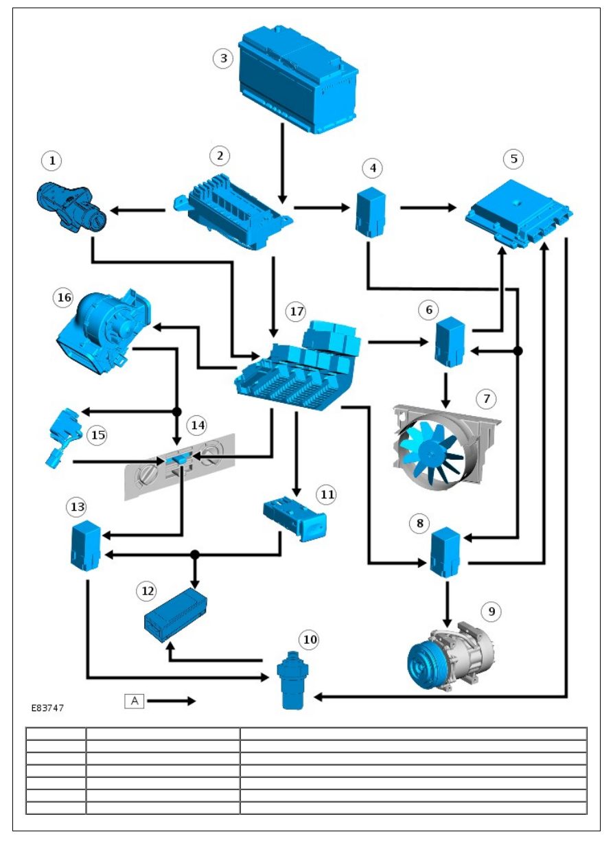
1
-
Ignition switch
2
-
battery junction box (BJB)
3
-
Battery
4
-
Main relay
5
-
ECM
6
-
Cooling fan relay

7
-
Cooling fan
8
-
A/C compressor clutch relay
9
-
A/C compressor clutch
10
-
A/C refrigerant pressure switch
11
-
A/C switch
12
-
A/C thermostatic switch
13
-
Blower motor relay
14
-
Blower motor switch
15
-
Blower motor resistor pack
16
-
Blower motor
17
-
central junction box (CJB)
PRINCIPLES OF OPERATION
Heating
Heating control is achieved by varying the amount of engine coolant fed into the heater matrix. Coolant is bled from the
engine cooling system and fed into the heater matrix through the water valve. The water valve is operated via a
Bowden cable from the rotary heater control and varies the amount of engine coolant entering the heater matrix in
response to heating demand.
If partial heating is requested, a proportion of engine coolant is returned back to the engine cooling system. If no
heating is requested, the water valve returns all engine coolant back to the engine cooling system, by-passing the
heater matrix.
Heat is transferred to the inlet air as it passes through the heater matrix. The heated air is then delivered into the cabin
through a series of ducts, vents, and registers.
For additional information, refer to:
Air Distribution and Filtering
(412-01 Air Distribution and Filtering, Description and
Operation).
Air Conditioning
The A/C system transfers heat from the cabin to the outside atmosphere to provide dehumidified cool air. The A/C
system is a sealed closed loop system, filled with a charge weight of R134a refrigerant as the heat transfer medium. Oil
is added to the refrigerant to lubricate the internal components of the A/C compressor.
Hot, high pressure gas from the compressor flows into the condenser, which allows heat to dissipate causing the gas to
condense into a liquid form. The flow of liquid refrigerant into the evaporator is controlled by the thermostatic expansion
valve. When in the evaporator the liquid refrigerant expands and absorbs heat from its surroundings, cooling the fins
and plates of the A/C evaporator. As inlet air passes across the A/C evaporator surface it is cooled before entering the
cabin through a series of ducts, vents, and registers.
For additional information, refer to:
Air Distribution and Filtering
(412-01 Air Distribution and Filtering, Description and
Operation).
Climate Control System - General Information - Climate Control System
Diagnosis and Testing
GENERAL PRECAUTIONS
The refrigerant used in the air conditioning system is HFC (Hydrofluorocarbon) R134a.
• WARNINGS:
R134a is a hazardous liquid and when handled incorrectly can cause serious injury. Suitable protective clothing
must be worn when carrying out servicing operations on the air conditioning system.
R134a is odourless and colourless. Do not handle or discharge in an enclosed area, or in any area where the
vapour or liquid can come in contact with naked flame or hot metal. R134a is not flammable, but can form a highly toxic
gas.
Do not smoke or weld in areas where R134a is in use. Inhalation of concentrations of the vapour can cause
dizziness, disorientation. uncoordination, narcosis, nausea or vomiting.
Do not allow fluids other than R134a or compressor lubricant to enter the air conditioning system. Spontaneous
combustion may occur.
R134a splashed on any part of the body will cause immediate freezing of that area. Also refrigerant cylinders and
replenishment trolleys when discharging will freeze skin to them if contact is made.
The refrigerant used in an air conditioning system must be reclaimed in accordance with the recommendations
given with a Refrigerant Recovery Recycling Recharging Station.
• NOTE: Suitable protective clothing comprises: Wrap around safety glasses or helmet, heatproof gloves, rubber apron
or waterproof overalls and rubber boots.
Routine servicing, apart from visual checks, is not necessary. The visual inspections are as follows:
Condenser
With a water hose or air line, clean the fins of the condenser to remove flies, leaves, etc. Check the pipe connections for
signs of oil leakage.
Compressor
Check pipe connections for signs of oil leakage. Check flexible hoses for swelling. Examine the compressor belt for
tightness and condition.
Sight glass
Examine the sight glass for bubbles with the system operating. Check connections for leakage.
Evaporator
Examine the refrigeration connections at the unit.
REMEDIAL ACTIONS
• WARNINGS:
Do not allow a refrigerant container to be heated by a direct flame or to be placed near any heating appliance. A
refrigerant container must not be heated above 50° C.
Do not leave a container of refrigerant without its cap fitted. Do not transport a container of refrigerant that is
unrestrained, especially in the boot of a car.
• NOTE: Due to its low evaporating temperature of -30° C, R134a should be handled with care.
If liquid R134a strikes the eye, do not rub it. Gently run large quantities of eyewash over the eye to raise the
temperature. If eyewash is not available cool, clean water may be used. Cover eye with clean pad and seek
immediate medical attention.
If liquid R134a is splashed on the skin run large quantities of water over the area as soon as possible to raise
the temperature. Carry out the same actions if skin comes into contact with discharging cylinders. Wrap affected
parts in blankets or similar material and seek immediate medical attention.
If suspected of being overcome by inhalation of R134a vapour seek fresh air. If unconscious remove to fresh air.
Apply artificial respiration and/or oxygen and seek immediate medical attention.
SERVICING PRECAUTIONS
Care must be taken when handling refrigeration system components. Units must not be lifted by their hoses, pipes or
capillary lines. Hoses and lines must not be subjected to any twist or stress. Ensure that hoses are positioned in their
correct run before fully tightening the couplings, and ensure that all clips and supports are used. Torque wrenches of the
correct type must be used when tightening refrigerant connections to the stated value. An additional spanner must be
used to hold the union to prevent twisting of the pipe.
Before connecting any hose or pipe ensure that refrigerant oil is applied to the seat of the new '0' ring but not to the
threads.
Check the oil trap for the amount of oil lost.
All protective plugs on components must be left in place until immediately prior to connection.
The receiver/drier contains desiccant which absorbs moisture. It must be positively sealed at all times.
CAUTION: Whenever the refrigerant system is opened, the receiver/drier must be renewed immediately before
evacuating and recharging the system.
Use alcohol and a clean cloth to clean dirty connections. Ensure that all new parts fitted are marked for use with R134a.
Refrigerant oil
Use the approved refrigerant lubricating oil - Nippon Denso ND-OIL 8.
CAUTION: Do not use any other type of refrigerant oil.
Refrigerant oil easily absorbs water and must not be stored for long periods. Do not pour unused oil back into the
container. When renewing system components, add the following quantities of refrigerant oil:
Component
Fluid quantity
Condenser
40ml
Evaporator
80ml
Pipe or hose
20ml
Receiver/drier
20ml
Total quantity of refrigerant oil in system
140ml
A new compressor is sealed and pressurised with Nitrogen gas, slowly release the sealing cap, gas pressure should be
heard to release as the seal is broken.
• NOTE: A new compressor should always have its sealing caps in place and these must not be removed until
immediately prior to fitting
A new compressor is supplied with an oil fill of 140ml.
A calculated quantity of oil must be drained from a new compressor before fitting.
To calculate the quantity of oil to be drained:
Remove sealing plugs from the OLD compressor.
Invert compressor and gravity drain oil into measuring cylinder. Rotating the compressor clutch plate will assist
complete draining.
Note the quantity of oil drained (Yml).
Calculate the quantity (Qml) of oil to be drained from the NEW compressor using the following formula: Xml -
(Yml + 20ml) = Qml
Rapid refrigerant discharge
When the air conditioning system is involved in accident damage and the circuit is punctured, the refrigerant is
discharged rapidly. The rapid discharge of refrigerant will also result in the loss of most of the oil from the system. The
compressor must be removed and all the remaining oil in the compressor drained and refilled as follows:
Gravity drain all the oil, assist by rotating the clutch plate (not the pulley).
Refill the compressor with 90ml of new refrigerant oil.
Plug the inlet and outlet ports.
Servicing Equipment
The following equipment is required for full servicing of the air conditioning system.
Recovery, recycling and charging station Leak detector Thermometer +20° C to -60° C Safety goggles and gloves
Precautions when handling refrigerant lines
Нет комментариевНе стесняйтесь поделиться с нами вашим ценным мнением.
Текст