Defender. Manual — part 240
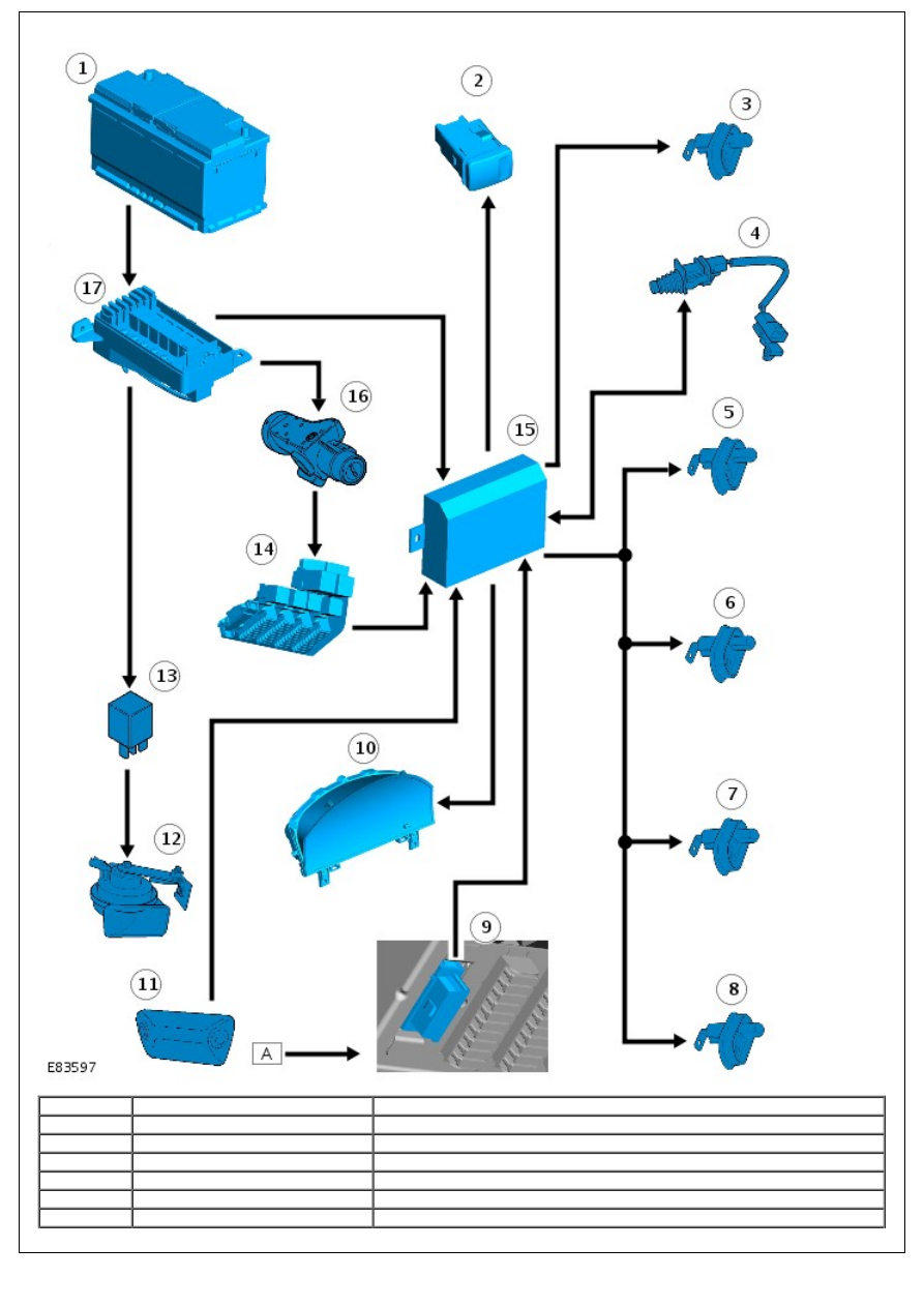
Item
Part Number
Description
1
-
Battery
2
-
Hazard flasher switch
3
-
Driver's door switch
4
-
Hood switch
5
-
Front passenger door switch
6
-
RH rear door switch (if fitted)

7
-
LH rear door switch (if fitted)
8
-
Tail door switch
9
-
Diagnostic socket
10
-
Instrument cluster
11
-
Intrusion detection module
12
-
Anti-theft alarm horn
13
-
Anti-theft alarm horn relay
14
-
CJB
15
-
Anti-theft system module
16
-
Ignition switch
17
-
BJB
PRINCIPLES OF OPERATION
On receipt of a valid code from the remote RF handset, the anti-theft system module will arm both the perimetric and
volumetric anti-theft systems. The anti-theft system module will also arm the passive immobilization system.
For additional information, refer to:
Anti-Theft - Passive
(419-01B Anti-Theft - Passive, Description and Operation).
Once armed, the anti-theft system can be triggered up to 3 times in any one arming cycle.
Perimetric Protection
Perimetric protection is the monitoring of each hinged panel, namely the doors, tail door and hood, for unauthorized
entry. The anti-theft system module monitors the condition of each hinged panel through a series of hardwired
connections.
The driver's door switch and the hood switch are connected to the anti-theft system module on individual wires. The
remaining hinged panels are wired in parallel and connected to the anti-theft system module on a single wire.
All the switches are open circuit. If a hinged panel is opened, the switch contacts close and a ground path is generated.
The switch ground paths are through the vehicle body, except for the hood switch which is provided a ground path via
the anti-theft system module. When the anti-theft system module registers a ground path it determines a hinged panel
has been opened and triggers the alarm.
Volumetric Protection
Volumetric protection monitors movement within the cabin. When the system is first armed, the anti-theft module
suspends volumetric protection for 15 seconds. This allows air in the cabin to settle and prevents nuisance triggers. The
anti-theft system module monitors movement in the vehicle cabin using the intrusion detection module. The anti-theft
system module will not initiate volumetric protection unless the intrusion detection module detects no disturbances for
15 seconds. If, during the 15 second arming period movement is detected, the 15 second period will re-start from 0.
Volumetric protection can be disabled in one of two ways:
By locking the vehicle with the key in the driver's door rather than using the remote RF handset.
By locking the vehicle with the remote RF handset while the driver's door is open. If the driver's door is
subsequently shut, only the perimetric system will be armed.
Visual Indications
• NOTE: Visual and audible warnings are dependent on market legislation.
When the anti-theft system is armed the anti-theft system module will flash the hazard flashers 3 times. The hazard
flashers are controlled by 2 outputs from the anti-theft system module; one for the LH lamps, one for the RH lamps. To
illuminate the hazard flashers, the output from the anti-theft system module is at battery voltage. To extinguish the
lamps, the output is driven to ground.
The anti-theft system module will also control operation of the instrument cluster indicator. The module will flash the
indicator at a rate of 8 Hz for 10 seconds, followed by a 1 Hz flashing rate.
If the anti-theft system is triggered, the anti-theft system module will flash the hazard flashers for 30 seconds at 0.5
second intervals.
Audible Indications
If the anti-theft system is triggered, the anti-theft system module will activate the sounder. Depending on market
legislation, the sounder is either an anti-theft alarm horn or a battery backed sounder. Again, depending on market
legislation, the sounder may emit either a continuous or pulsed tone.
The anti-theft system module provides a battery voltage feed to, depending on vehicle specification, the battery backed
sounder or the anti-theft alarm horn relay. To power the sounder, the anti-theft system module removes the feed and
provides a ground path.
Anti-Theft - Passive - Anti-Theft - Passive
Description and Operation
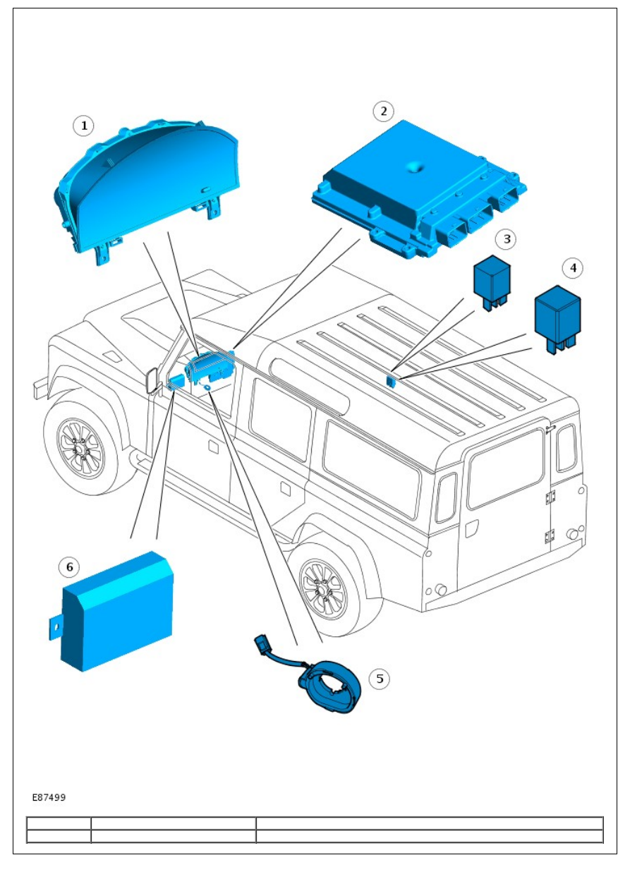
COMPONENT LOCATION
Item
Part Number
Description
1
-
Instrument cluster
2
-
engine control module (ECM)
3
-
Starter relay
4
-
Glow plug relay
5
-
Transceiver coil
6
-
Anti-theft system module
OVERVIEW
The 10AS anti-theft system works in conjunction with the ECM to control the passive anti-theft system. The passive
anti-theft system immobilizes the engine by inhibiting the starter relay and fuel injectors until a valid code is received
from the remote Radio Frequency (RF) handset.
The passive anti-theft system features 2 levels of protection:
Engine immobilization only
Engine immobilization plus perimetric and volumetric anti-theft alarm protection.
For additional information, refer to:
Anti-Theft - Active
(419-01A Anti-Theft - Active, Description and Operation).
The anti-theft system module activates the engine immobilization system 30 seconds after the key is removed from the
ignition switch and the driver's door is opened. If the key is removed from the ignition switch and the drivers door isn't
opened, the anti-theft system module will activate the engine immobilization system after a period of 5 minutes.
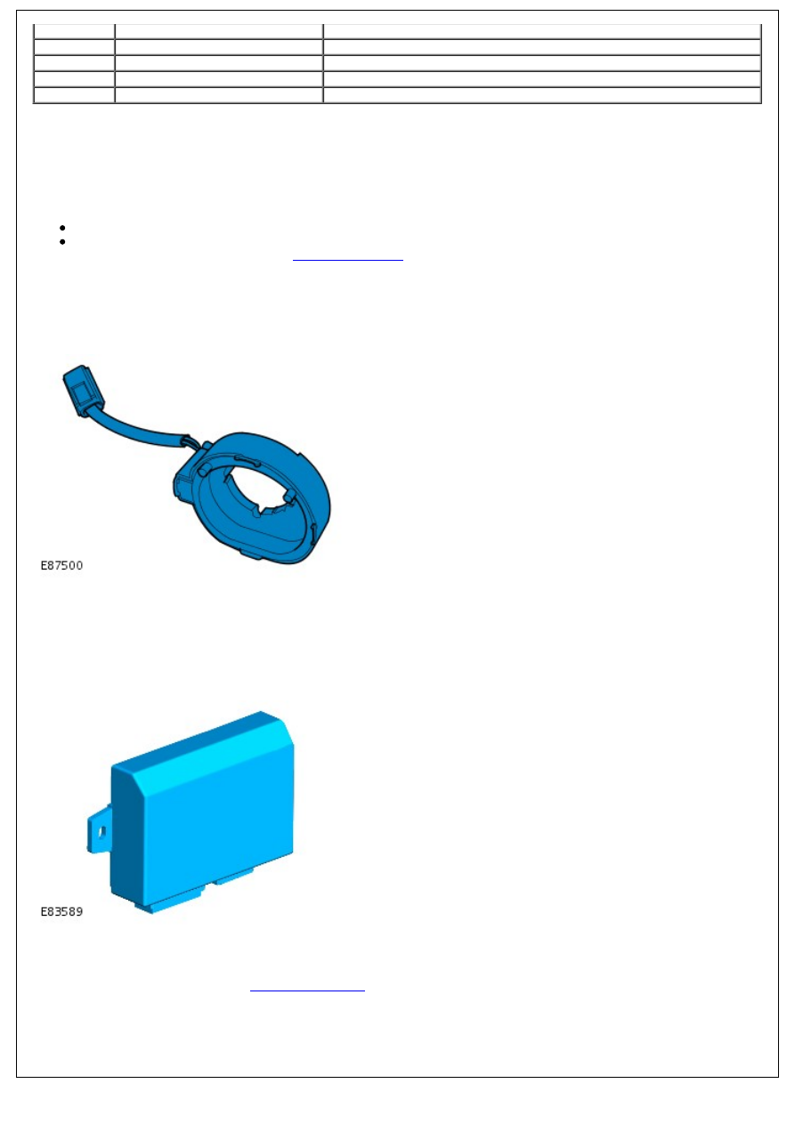
TRANSCEIVER COIL
The transceiver coil comprises a coil mounted around the ignition barrel. When the ignition switch is turned to position
II, the anti-theft system module provides a permanent battery voltage feed and a pulsed voltage feed to the transceiver
coil. This creates a magnetic field around the ignition barrel, which collapses and restores in relation to the pulsed power
feed from the anti-theft system module. The fluctuating magnetic field activates the remote RF handset which transmits
a mobilization signal.
ANTI-THEFT SYSTEM MODULE
The anti-theft system module is located behind the instrument cluster and works in conjunction with the ECM to control
the passive anti-theft system. The anti-theft system module receives a permanent battery supply from the battery
junction box (BJB) and an ignition switch supply from the central junction box (CJB).
For additional information, refer to:
Battery and Cables
(414-01 Battery, Mounting and Cables, Description and
Operation).
A mobilization code is transmitted to the anti-theft system module by the remote RF handset. The mobilization code is
received via the anti-theft system module antenna, which hangs below the module. The anti-theft system module
determines if a valid code is received from the remote RF handset by comparing the received code with one stored in its
Нет комментариевНе стесняйтесь поделиться с нами вашим ценным мнением.
Текст