Defender. Manual — part 187
2.
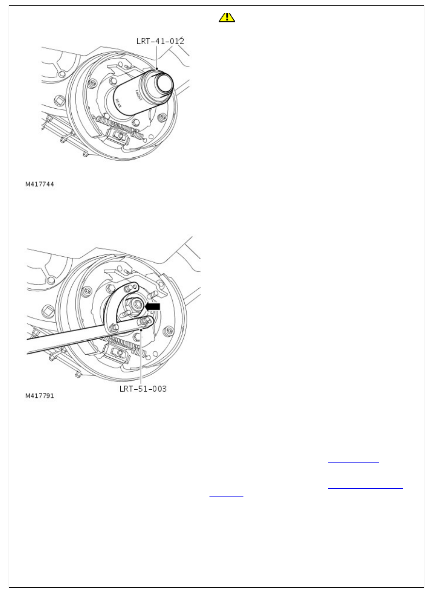
CAUTION: Oil seal must be fitted dry.
Install new seal using LRT-41-012 .
• NOTE: Use end of tool marked 'REAR' to instal seal.
3. Position drive flange, instal new felt and steel washers.
4. Position LRT-51-003 instal and tighten new drive flange
nut to 148 Nm (109 lbf.ft).
5. Position brake drum and tighten screw.
6. Tighten adjuster bolt to 25 Nm (18 lbf.ft) then back off 1 !
turns.
7. Check that brake drum is free to rotate.
8. Install drive shaft.
For additional information, refer to:
Rear Driveshaft
(205-01
Driveshaft, Removal and Installation).
9. Top-up transfer case oil.
For additional information, refer to:
Transfer Case Draining
and Filling
(308-07A Transfer Case - 2.4L Duratorq-TDCi
HPCR (103kW/140PS) - Puma, General Procedures).

Transfer Case - 2.4L Duratorq-TDCi HPCR (103kW/140PS) - Puma -
Transfer Case
Removal
Special Tool(s)
Power train Assembly Jack
HTJ1200-02
Transfer Case Support
100-045
Removal
1. Release the parking brake lever gaiter.
Release the 3 clips.
2. Remove the parking brake lever clevis pin.
Remove the pin.
3.
WARNING: Do not work on or under a vehicle
supported only by a jack. Always support the vehicle on safety
stands.
Raise and support the vehicle.
4. Release the intermediate pipe from the catalytic converter.

4. Release the intermediate pipe from the catalytic converter.
Remove and discard the 2 nuts.
5. Release the tail pipe from the intermediate pipe.
Remove and discard the 3 nuts.
Remove and discard the gasket.
6. Remove the intermediate pipe and muffler.
7. NOTE: Mark the front driveshaft to transfer case drive
flange.
Remove and discard the 4 nuts.
Using a suitable tie strap, secure the driveshaft to one
side.
8. Remove the 4 nuts from the rear driveshaft to transfer

8. Remove the 4 nuts from the rear driveshaft to transfer
case.
Mark the position of the driveshaft in relation to the
drive pinion flange.
9. Using a suitable tie strap, secure the rear driveshaft to the
chassis.
10. Disconnect the electronic speedometer electrical
connector from the transfer case.
11. Disconnect the LH earth cable from the transfer case.
Remove the nut.
12. Disconnect the RH earth cables from the transfer case.
Нет комментариевНе стесняйтесь поделиться с нами вашим ценным мнением.
Текст