Defender. Manual — part 293
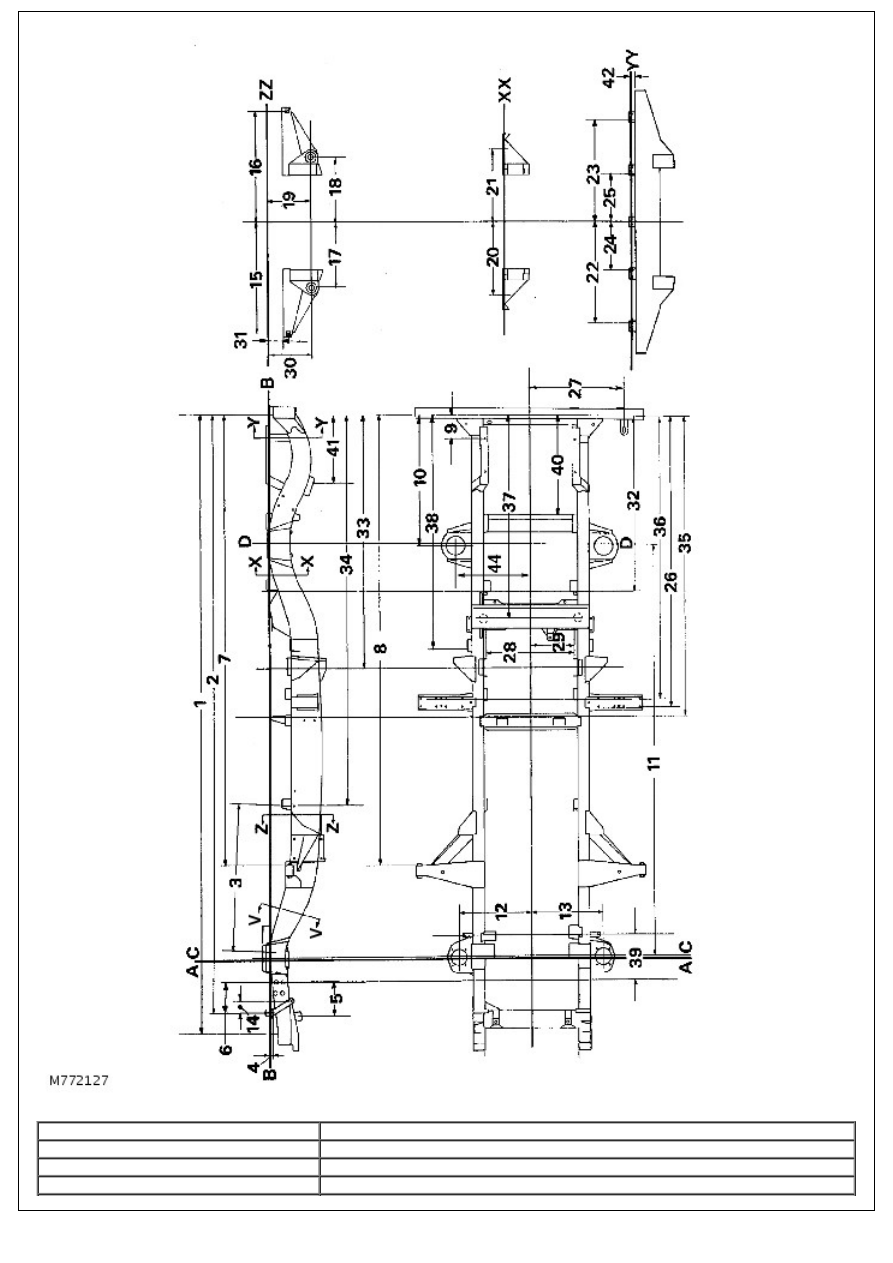
Chassis alignment dimensions
No./Letter
Dimension
A
Front datum
B
Chassis Datum
C
Front axle centre line
D
Rear axle centre line
1.
4148 - 4143 mm
2.
4009,5 - 4005 mm
3.
978,7 - 981,2 mm
4.
22 - 20 mm
5.
252 - 250 mm
6.
239 - 236,5 mm
7.
3023,3 - 3022,3 mm
8.
3030,7 - 3028,7 mm
9.
155 - 153 mm
10.
871,2 - 869,2 mm
11.
2794 mm - Wheelbase
12.
488 - 482 mm
13.
488 - 482 mm
14.
82 - 79,5 mm
15.
750,9 mm
16.
750,9 mm
17.
440,5 - 435,5 mm
18.
440,5 - 435,5 mm
19.
299,5 - 295,5 mm
20.
500 - 495 mm
21.
500 - 495 mm
22.
594,2 - 593,4 mm
23.
594,2 - 593,4 mm
24.
283 - 282,2 mm
25.
283 - 282,2 mm
26.
1970 - 1968 mm
27.
642,9 - 639,5 mm
28.
750,9 mm
29.
290,5 mm
30.
295,5 mm
31.
299,5 - 295,5 mm
32.
103 - 100 mm
33.
1177,5 - 1175,5 mm
34.
1692,5 - 1689,5 mm
35.
2610 - 2606 mm
36.
2040,5 - 2037,5 mm
37.
1912,5 - 1909,5 mm
38.
1359 - 1357 mm
39.
1573 - 1571 mm
40.
270 - 268 mm
41.
665,5 - 663,5 mm
42.
440 - 438 mm
43.
32,25 - 31,25 mm
Section V-V is through the engine mountings. Dimensional information can be found in the 90 engine mounting
dimensions.
130 Chassis
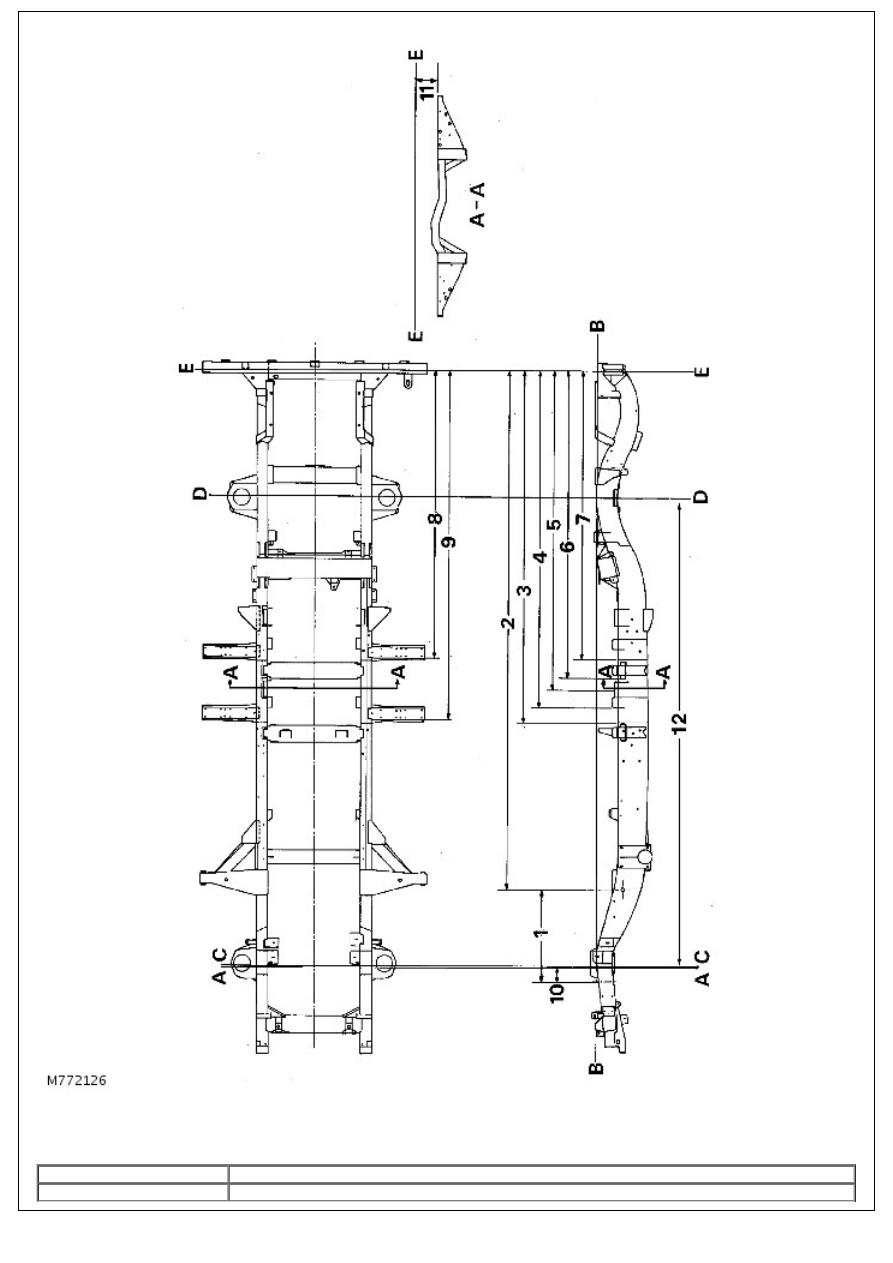
Chassis alignment dimensions
• NOTE: The above dimensions are for the Land Rover 130 chassis frame. For additional measurements, refer to the
Land Rover 110 chassis frame drawing and alignment dimensions.
No./Letter
Dimension
A
Front datum
B
Chassis Datum
C
Front axle centre line
D
Rear axle centre line
E.
Chassis Datum, section A-A
1.
663,0 mm reference only
2.
3569,3 - 3567,3 mm
3.
2421,8 - 2419,8 mm
4.
2317,5 - 2314,5 mm
5.
2188,3 - 2185,3 mm
6.
2119,5 - 2117,3 mm
7.
1990 - 1988 mm
8.
1970 - 1968 mm
9.
2401,8 - 2399,8 mm
10.
110,0 mm reference
11.
149,7 - 146,7 mm reference dimension
12.
3225,8 mm wheelbase
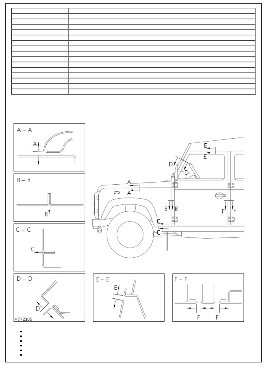
GAP AND PROFILE INFORMATION
The following information is to be used as a guide to assist the technician in refitting exterior body panels and trim
items, to achieve a correctly aligned and cosmetically acceptable vehicle.
Section A-A, Bonnet to wing gap A = 3 - 8 mm. To be parallel within 2 mm
Section B-B, Wing to 'A' post lower, gap B = 0. Profile = ± 1 mm
Section C-C, Wing to sill, gap C = 0. Profile = ± 1 mm
Section D-D, Screen aperture to door frame , gap D = 5 - 9 mm
Section E-E, Door frame to roof, gap E = 7 - 11 mm
Section F-F, Front and rear door to 'B'/'C' post, gap F = 7 - 11 mm
Нет комментариевНе стесняйтесь поделиться с нами вашим ценным мнением.
Текст