Defender 300Tdi (1996+). Manual — part 16

ENGINE
7
REPAIR
Refit
12. Lightly grease pulley spigot and locate pulley
onto cranshaft.
13. Fit pulley retaining bolt.
14. Fit pulley retainer LRT-12-080 and secure with 4
bolts.
15. Tighten pulley nut to
80 Nm (59 lbf/ft) + 90
°
.
16. Remove pulley retainer.
17. Fit drive belt.
See ELECTRICAL, Repair,
Auxiliary drive belt; Refit
18. Fit fan cowl.
See COOLING SYSTEM, Repair,
Fan cowl
19. Fit viscous coupling and fan.
See COOLING
SYSTEM, Repair, Viscous coupling and fan
20. Fit intercooler to induction manifold hose.
21. Fit radiator top hose.
22. Refill cooling system.
See COOLING SYSTEM,
Repair, Drain and refill cooling system
23. Reconnect battery.
FRONT COVER PLATE AND SEAL
Service repair no - 12.65.01
Remove
1. Disconnect battery.
2. Drain coolant.
See COOLING SYSTEM,
Repair, Drain and refill cooling system
3. Remove top hose from radiator.
4. Remove intercooler to induction manifold hose.
5. Remove viscous coupling and fan.
See
COOLING SYSTEM, Repair, Viscous
coupling and fan
6. Remove fan cowl.
See COOLING SYSTEM,
Repair, Fan cowl
7. Remove drive belt.
See ELECTRICAL, Repair,
Auxiliary drive belt
8. Remove crankshaft pulley.
See Crankshaft
pulley
9. Remove 14 bolts securing front cover plate. Note
that top 2 bolts also retain thermostat hose clips.
10. Remove cover plate complete with gasket.
11. Remove small gasket from centre bolt boss.
Seal replacement
12. Remove worn seal from cover and clean recess.
13. Support cover and fit new seal, open side fitted
into recess, using special tool LRT-12-077.
12
ENGINE
8
REPAIR
Refit
14. Fit gasket to centre bolt boss.
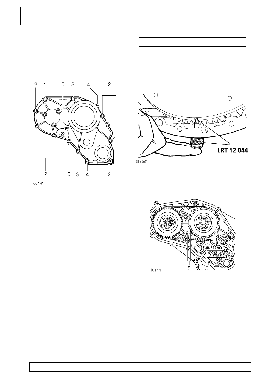
15. Locate new gasket and fit front cover plate using
fixing bolts as shown. Tighten bolts to
25 Nm (18
lbf/ft).
1 - 25 mm, 2 - 35 mm, 3 - 50 mm, 4 - 100 mm, 5 - 110
mm
16. Fit crankshaft pulley.
See Crankshaft pulley
17. Fit drive belt.
See ELECTRICAL, Repair,
Auxiliary drive belt
18. Fit fan cowl.
See COOLING SYSTEM, Repair,
Fan cowl
19. Fit viscous coupling and fan.
See COOLING
SYSTEM, Repair, Viscous coupling and fan
20. Fit intercooler to induction manifold hose.
21. Fit top hose to radiator.
22. Refill cooling system.
See COOLING SYSTEM,
Repair, Drain and refill cooling system
23. Reconnect battery.
CAMSHAFT DRIVE BELT
Service repair no - 12.65.18
Remove
1. Remove front cover plate.
See Front cover
plate
2. Position engine at TDC on No. 1 cylinder.
3. Remove blanking plug from flywheel housing
and insert timing tool LRT-12-044.
4. Engage timing tool pin with slot in flywheel.
5. Check correct alignment of timing mark on
camshaft gear and that crankshaft key aligns
with cast arrow on housing.
6. Insert pin from special tool LRT-12-045 in
injection pump gear and through into pump
flange.
ENGINE
9
REPAIR
NOTE: If the camshaft gear is to be
removed during these operations its
retaining bolt should be slackened before
the timing belt is removed.
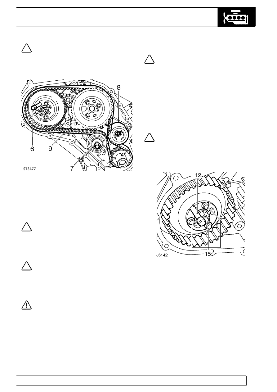
7. Slacken belt tensioner bolt.
8. Remove idler pulley.
9. Remove timing belt.
NOTE: If excessive timing belt debris is
evident in the front cover, this is probably
due to the misalignment of the front timing
cover caused by incorrect assembly of the fuel
injection pump bracket.
See FUEL SYSTEM,
Repair, Fuel Injection pump
NOTE: During use, a belt develops a wear
pattern relative to its running direction, if
the original belt is to be re-used it must be
refitted so that it rotates in the original direction.
Mark belt direction of rotation, using soft chalk, to
ensure correct refitment.
CAUTION: The belt must be stored on its
edge on a clean surface and in such a
manner that bends are not less than 50
mm (2.0in.) radius. Do not bend belts at an acute
angle, otherwise premature failure could result.
Belt tensioner
NOTE: The belt tensioner need only be
removed if it is being replaced or for
access purposes to remove front cover.
10. Remove securing bolt and withdraw tensioner
complete with spacer.
Refit
11. If necessary, fit belt tensioner and spacer.
Tighten fixing bolt to
45 Nm (33lbf/ft).
Timing belt fitting and tensioning
NOTE: It is important that belt tensioning
is carried out carefully and accurately. The
following procedure involves tensioning
the belt twice to ensure that it is equally tensioned
between each gear. New and original belts are
tensioned to different figures.
12. Ensure timing marks are correctly aligned, pin
from special tool LRT-12-045 is correctly
inserted in injection pump gear and timing tool
LRT-12-044 is fitted to flywheel housing with pin
located in flywheel slot.
13. Fit belt, observing rotational marks made during
removal. Feed belt over gears keeping it tight on
drive side.
14. Fit idler pulley.
15. Slacken injection pump gear retaining bolts.
16. Adjust belt to correctly sit in gears.
12
ENGINE
10
REPAIR
17. Slacken belt tensioner securing bolt to finger
tight.
18. Insert 13 mm square drive extension bar in
tensioner plate.
NOTE: Belt tensioning should be carried
out using a dial type torque meter having a
range not exceeding
60 Nm (44 lbf/ft). The
torque meter should be used in the almost vertical
position.
19. Apply a tension of
15 Nm (11 lbf/ft) for a new
belt or
12 Nm (9 lbf/ft) for an original belt. When
tension is correct, tighten clamp bolt.
20. Tighten injection pump gear bolts.
21. Remove pin from injection pump gear.
22. Disengage timing pin from timing slot in flywheel
or ring gear.
23. Rotate crankshaft one and three quarter turns in
a clockwise direction; then continue rotation until
timing pin in timing tool can be engaged with slot
in flywheel.
24. Disengage timing pin.
25. Insert pin from special tool LRT-12-045 in
injection pump gear and through into pump
flange.
26. Slacken injection pump gear retaining bolts.
27. Slacken tensioner and retension belt.
28. Tighten injection pump gear retaining bolts.
29. Remove pin from injection pump gear.
30. Remove timing tool and refit plug.
31. Fit front cover plate using new gaskets.
See Front cover plate and seal
CRANKSHAFT GEAR
Service repair no - 12.65.25
Remove
1. Remove camshaft drive belt.
See Camshaft
drive belt
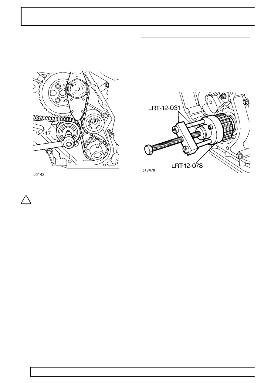
2. If the crankshaft gear cannot be removed by
hand, use special tool LRT-12-078 with main
body and thrust button from special tool
LRT-12-031, as illustrated . Withdraw gear
complete with ’O’ ring seal.
Refit
3. Lubricate new ’O’ ring seal with petroleum jelly
and slide onto crankshaft, taking care not to
damage seal on woodruff keys.
4. Fit crankshaft gear and tap fully home ensuring
’O’ ring seal is properly seated.
5. Fit camshaft drive belt.
See Camshaft drive
belt
Нет комментариевНе стесняйтесь поделиться с нами вашим ценным мнением.
Текст