Defender 300Tdi (1996+). Manual — part 62
STEERING
15
REPAIR
15. Centralise steering box
See Adjustment,
Centralise steering box .
16. Align steering wheel, if necessary.
CAUTION: A drag link that is damaged or
bent must be renewed. DO NOT attempt
repair.
17. Fit drag link to swivel housing arms and tighten
nuts to
40 Nm (30 lbf/ft). Fit new split pins.
18. Ensure full steering travel is obtained between
lock stops
See Adjustment, Steering lock
stops . Adjust drag link length to suit.
19. Tap ball joints in direction shown so both pins
are in same angular plane.
20. Tighten clamp bolts to
14 Nm (10 lbf/ft).
21. Refit road wheel and remove axle stands or
vehicle from ramp.
22. Road test vehicle.
23. If driving straight ahead and steering wheel is
offset by 0
° ±
5
°
in either direction, correct by
adjusting drag link length.
WARNING: To correct steering wheel
deviations greater than
±
5
°
remove and
reposition steering wheel
See Steering
wheel .
STEERING
1
OVERHAUL
POWER STEERING BOX - ADWEST
Service repair no - 57.10.07
Overhaul
NOTE: Overhaul of steering box should
not be carried out during the warranty
period.
WARNING: Wear safety glasses while
removing and refitting circlips and
retaining ring.
CAUTION: Absolute cleanliness is
essential when overhauling power steering
box.
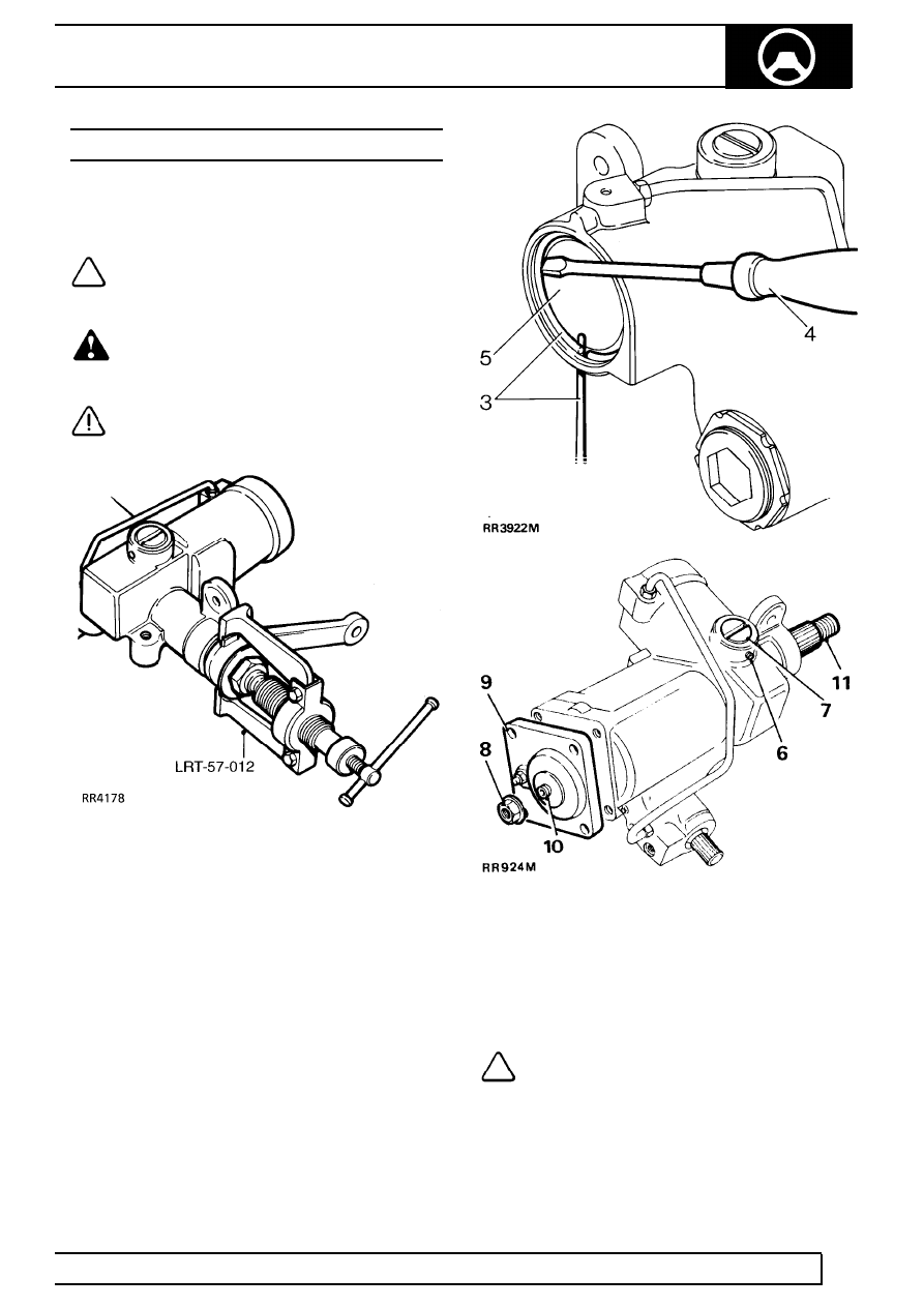
1. Remove steering box from vehicle
See Repair,
Power Steering Box . Mark drop arm and
steering box for realignment on assembly.
Remove drop arm using extractor LRT-57-012.
Loosen drop arm securing nut, but do not
remove before using extractor. Remove dirt
excluder from output shaft.
2. Drain oil, remove blanking plugs and bleed
screw. Hold steering box over suitable container,
turn input shaft from lock to lock, until oil is
drained. Refit bleed screw.
3. Rotate retainer ring until one end is 12 mm from
extractor hole. Using a drift through hole in
cylinder, lift retaining ring from groove in cylinder
bore.
4. Remove retainer ring, using a screwdriver.
5. Turn input shaft (left lock on left hand drive, right
lock on right hand drive) until piston pushes out
cover. Turn input shaft fully in opposite direction,
applying pressure to piston.
6. Remove set screw retaining rack pad adjuster.
7. Remove rack adjuster and pad.
8. Remove sector shaft adjuster locknut.
9. Remove four bolts from sector shaft cover.
10. Screw in sector shaft adjuster until cover is
removed.
NOTE: Sealant is applied to hexagon
socket to ’tamperproof’ sector shaft
adjuster.
11. Slide out sector shaft.
57
STEERING
2
OVERHAUL
12. Remove piston, a bolt screwed into piston will
assist removal.
13. Remove input shaft dirt excluder.
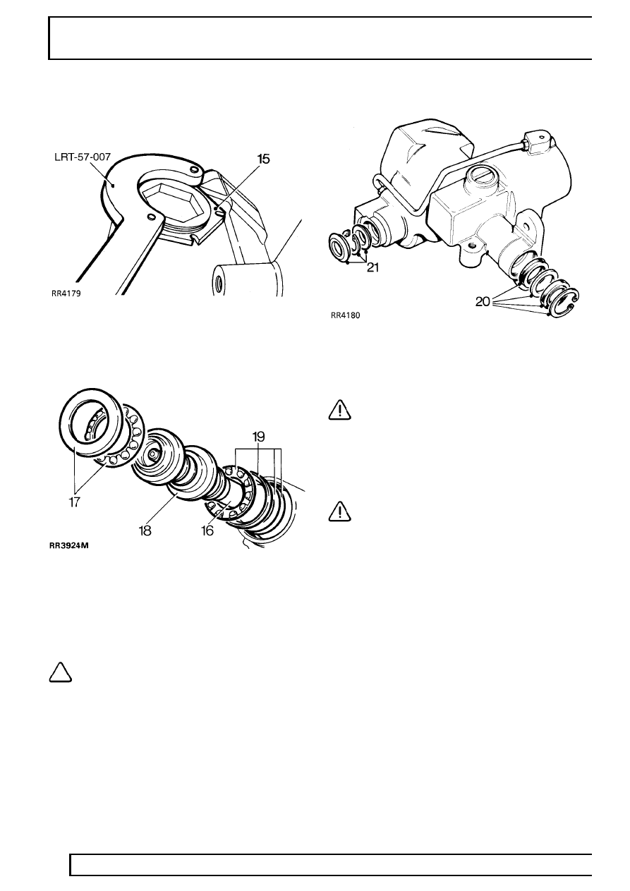
14. Remove worm adjuster locknut using ’C’ wrench
LRT-57-007.
15. Remove worm adjuster using wrench
LRT-57-006.
16. Tap splined end of shaft to free bearing.
17. Remove bearing cup and caged ball bearing
assembly.
18. Remove valve and worm assembly.
19. Remove inner bearing cage, cup and shim
washers. Retain shims for reassembly.
NOTE: Should difficulty be experienced
warm casing and bearing assembly. Cool
bearing cup using a mandrel and tap
steering box on a bench.
Steering box seals
20. Remove circlip and seal from sector shaft
housing bore.
CAUTION: Do not remove sector shaft
bearings from casing. Replacement parts
are not available. If sector shaft bearings
are worn fit a new steering box.
21. Remove dirt excluder, circlip and seal from input
shaft housing bore.
CAUTION: The use of a seal puller is
recommended to prevent damage to
casing, and possible oil leaks.
STEERING
3
OVERHAUL
INSPECTING
Piston
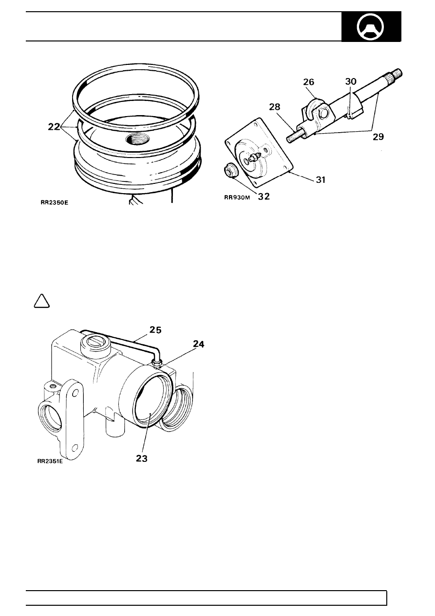
22. Discard all rubber seals and obtain
replacements.
NOTE: A rubber seal is fitted behind
plastic ring on rack piston. Discard seal
and plastic ring.
Steering box casing
23. Examine piston bore for scoring and wear.
24. Examine feed tube.
25. Fit a new feed tube if damaged. Tighten union to
22 Nm (16 lbf/ft).
Sector shaft assembly
26. Check there is no side play on roller.
27. If side play on roller exists fit a new sector shaft.
28. Check condition of adjuster screw threads.
Check adjuster end float. Fit new adjuster if end
float exceeds 0.15 mm.
29. Examine bearing areas on shaft for excessive
wear.
30. Examine gear teeth for uneven or excessive
wear.
Sector shaft cover assembly
31. Inspect cover and bearing. If worn or damaged,
fit a new steering box.
Sector shaft adjuster locknut
32. The locknut is also a fluid seal. Fit new nut at
overhaul.
Нет комментариевНе стесняйтесь поделиться с нами вашим ценным мнением.
Текст