Defender 300Tdi (1996+). Manual — part 60
STEERING
7
REPAIR
POWER STEERING PUMP
Service repair no - 57.20.14
Remove
NOTE: A chassis undertray may be fitted
on some vehicle derivatives to conform to
legal requirements. When under chassis
remove and refit procedures are required, it may
be necessary to remove the undertray
See
CHASSIS AND BODY, Repair, Front undertray .
1. Disconnect battery.
2. Remove viscous fan unit
See COOLING
SYSTEM, Repair, Viscous coupling and fan .
3. Restrain steering pump pulley, slacken but do
not remove 3 bolts securing pulley.
4. Remove drive belt
See ELECTRICAL, Repair,
Auxiliary drive belt .
5. Remove bolts and remove pulley.
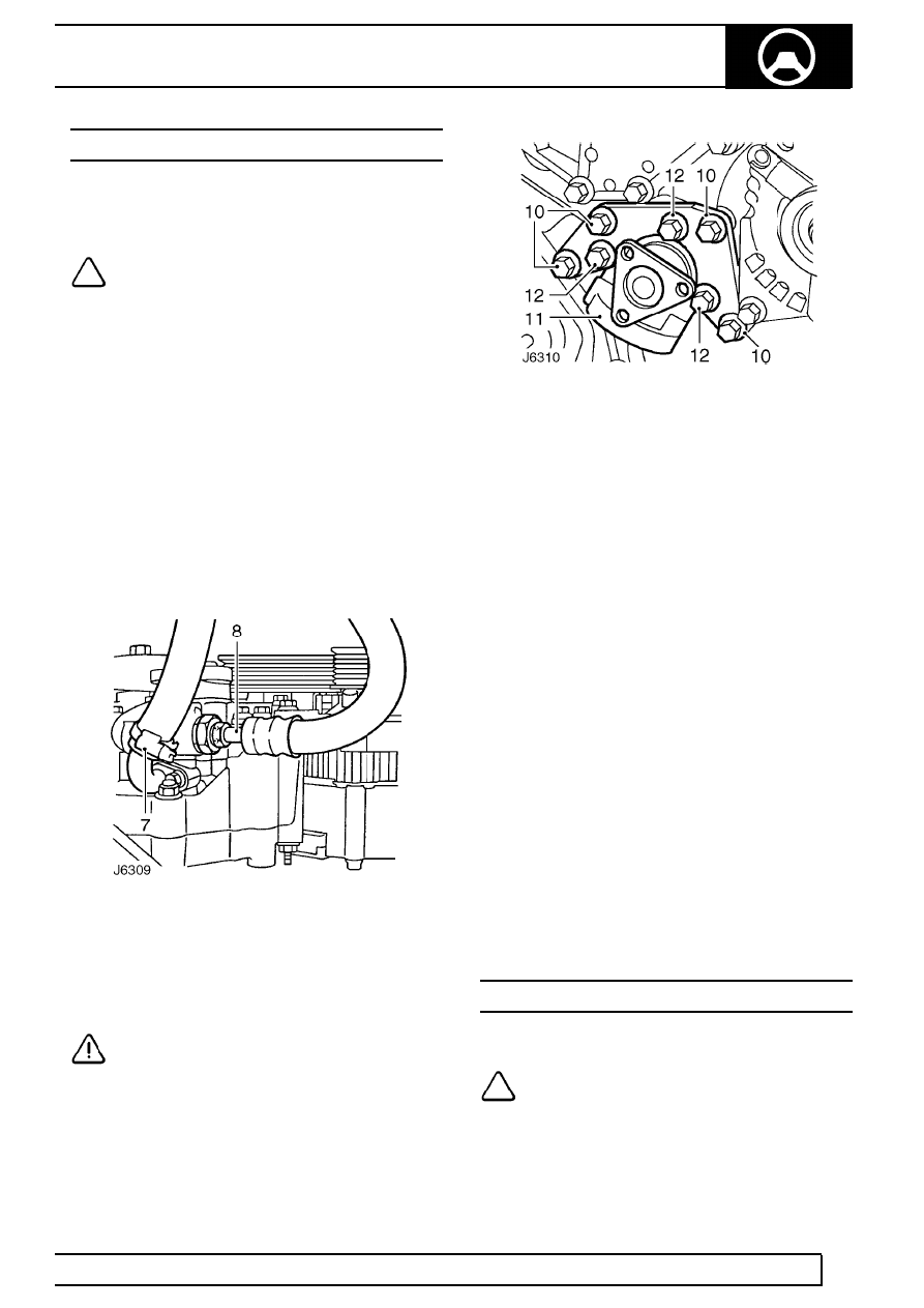
6. Position suitable container beneath steering
pump.
7. Slacken retaining clip and disconnect return
hose from steering pump.
8. Disconnect high pressure pipe from steering
pump.
9. Allow steering fluid to drain into container.
CAUTION: Plug all connections to prevent
ingress of dirt.
10. Remove 4 bolts securing steering pump bracket
to engine auxiliary mounting bracket.
11. Remove pump and bracket assembly.
12. Remove 3 bolts and detach mounting bracket
from pump.
Refit
13. Fit mounting bracket to replacement steering
pump. Tighten bolts to
9 Nm (7 lbf/ft).
14. Fit pump and bracket to auxiliary mounting
bracket. Tighten bolts to
35 Nm (26 lbf/ft).
15. Connect high pressure feed pipe to steering
pump and tighten to
20 Nm (15 lbf/ft).
16. Connect return hose to steering pump. Tighten
retaining clip to
3 Nm (2 lbf/ft).
17. Position pulley to steering pump, coat threads of
bolts with Loctite 242; fit but do not fully tighten
bolts.
18. Fit drive belt
See ELECTRICAL, Repair,
Auxiliary drive belt .
19. Restrain steering pump pulley, tighten bolts to
10
Nm (7lbf/ft).
20. Fit viscous fan unit
See COOLING SYSTEM,
Repair, Viscous coupling and fan .
21. Bleed power steering system
See Power
steering system - bleed .
POWER STEERING PUMP DRIVE BELT
Service repair no - 57.20.02
NOTE: For details of drive belt remove and
refit
See ELECTRICAL, Repair, Auxiliary
drive belt .
57
STEERING
8
REPAIR
LOWER STEERING SHAFT AND UNIVERSAL
JOINTS
Service repair no - 57.40.16
Remove
1. Remove vehicle bonnet.
2. Set road wheels and steering wheel in straight
ahead position.
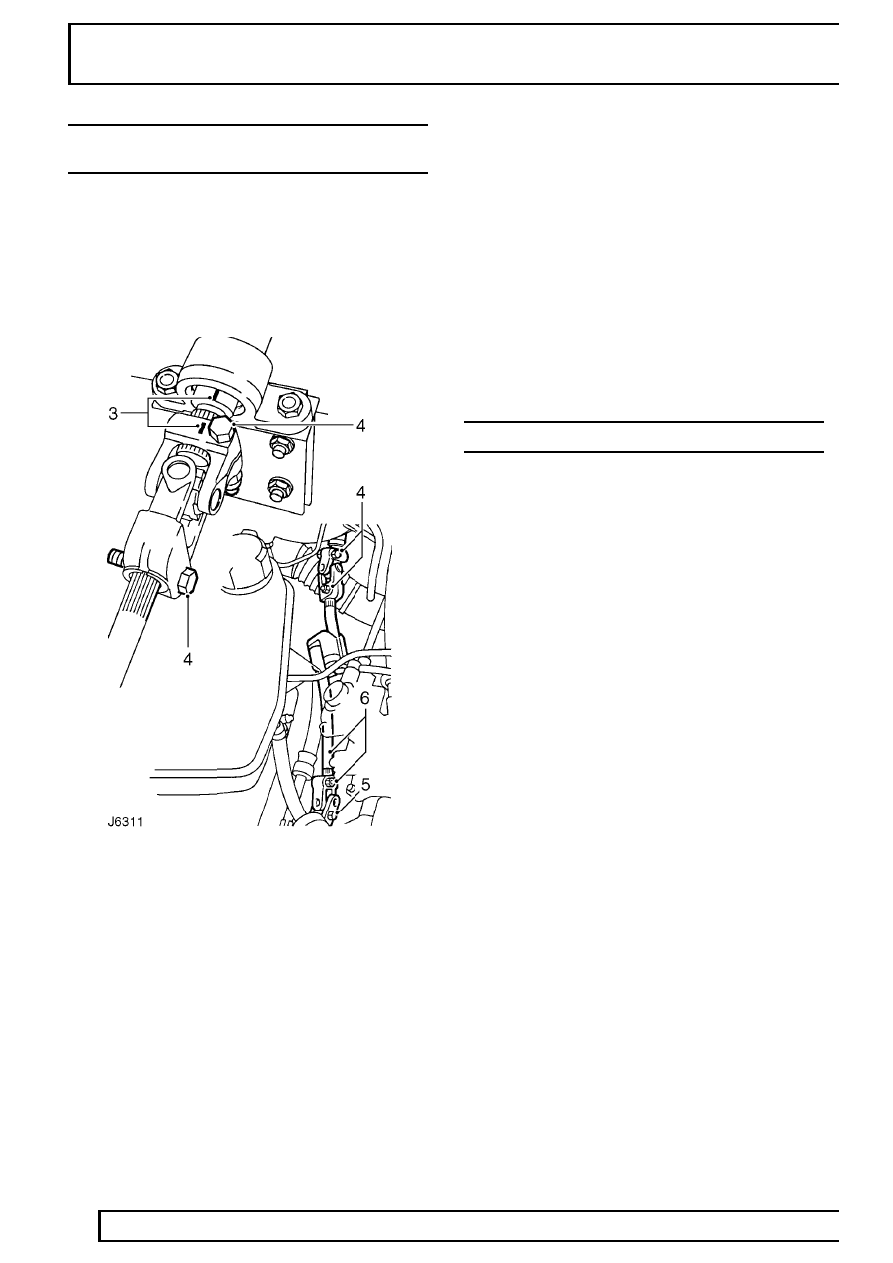
3. Mark relationship of steering column inner shaft
to top universal joint.
4. Remove 2 bolts from top universal joint.
5. Remove lower bolt from bottom universal joint.
6. Slacken upper bolt of lower universal joint and
withdraw shaft.
7. Inspect upper and lower universal joints for wear
and excessive play, renew if necessary.
8. Inspect universal joints for stiffness, lubricate if
necessary.
Refit
9. Fit universal joints so pinch bolt holes line up
with flat on shaft. Note that the long joint is fitted
to short length of shaft and short joint to long
end.
10. With steering lock engaged and road wheels in
straight ahead position, line up assembly marks.
11. Position shaft assembly onto steering column.
Move assembly up spline to enable lower
universal joint to fit onto steering box splines.
12. Align bolt holes with grooves in splines. Fit pinch
bolts and tighten to
25 Nm (18 lbf/ft).
STEERING WHEEL
Service repair no - 57.60.01
Remove
1. Set road wheels and steering wheel in straight
ahead position.
2. Prise decal from steering wheel pad.
3. Remove retaining nut and shakeproof washer.
Make alignment marks on column and wheel
pad.
4. Withdraw steering wheel from column spline.
Refit
5. Turn indicator cancelling ring so that slots are
vertical and lug with arrow points to the left, in
direction of indicator switch.
6. Ensure front road wheels are in straight ahead
position.
7. Fit steering wheel with finisher attachment lug at
the bottom, ensuring indicator cancelling forks
locate in cancelling ring slots. Align assembly
marks.
8. Secure wheel with retaining nut and new
shakeproof washer. Tighten to
25 Nm (18 lbf/ft).
STEERING
9
REPAIR
STEERING COLUMN LOCK
Service repair no - 57.40.28
Remove
1. Disconnect battery.
2. Set road wheels in straight ahead position.
3. Remove steering wheel
See Steering wheel .
4. Remove instrument panel
See INSTRUMENTS,
Repair, Instrument panel .
5. Remove steering column nacelle
See Steering
column nacelle .
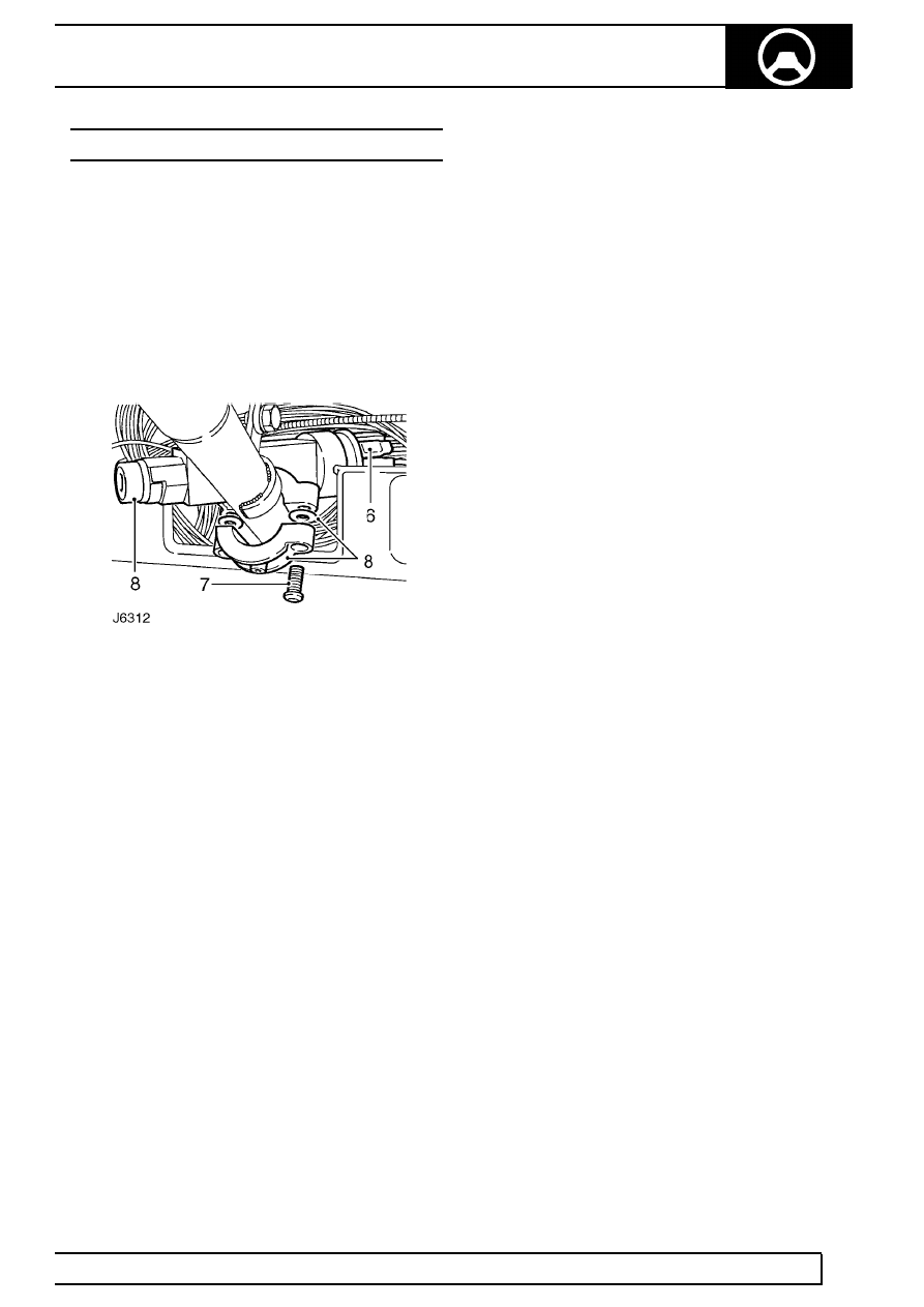
6. Note position of harness leads on back of starter
switch and disconnect lucars. If fitted, remove
alarm system passive coil from switch
See
ELECTRICAL, Repair, Vehicle immobilisation
and alarm system .
7. Using a punch or stud extractor remove 2 shear
bolts securing steering lock/starter switch to
column.
8. Remove steering lock and collect 2 washers
between lock and clamp.
Refit
9. Fit steering lock/switch in position and line up
with switch plunger.
10. Secure lock to column with clamp and new shear
bolts. Evenly tighten bolts but do not shear them.
11. Temporarily fit steering wheel and operate lock
and switch mechanism to ensure it functions
correctly.
12. Fully tighten retaining bolts until heads shear.
13. Connect harness leads to rear of starter switch.
If applicable, fit alarm system passive coil
See
ELECTRICAL, Repair, Vehicle immobilisation
and alarm system .
14. Fit steering column nacelle
See Steering
column nacelle .
15. Fit instrument panel
See INSTRUMENTS,
Repair, Instrument panel .
16. Fit steering wheel
See Steering wheel .
17. Reconnect battery.
57
STEERING
10
REPAIR
STEERING COLUMN NACELLE
Service repair no - 57.40.29
Remove
1. Disconnect battery.
2. Remove steering wheel
See Steering wheel .
3. Remove 5 screws and 2 self tapping screws and
lift top half of nacelle from steeering column
switch assembly.
4. Ease bottom half of nacelle from switch
gaiters/grommets. Remove lower nacelle.
Refit
5. Locate top half of nacelle in position and fit to
switch assembly gaiters/grommets.
6. Locate lower half of nacelle and loosely fit
retaining screws.
7. Ensure switch gaiters/grommets are correctly
located and nacelle is aligned with switch
assembly brackets.
8. Fully tighten screws.
9. Fit steering wheel
See Steering wheel .
10. Reconnect battery.
DROP ARM
Service repair no - 57.50.14
Remove
1. Park vehicle on level surface and chock rear
wheels.
2. Raise vehicle and locate axle stands or use a
ramp.
3. Disconnect steering damper from drag link
See
Steering damper .
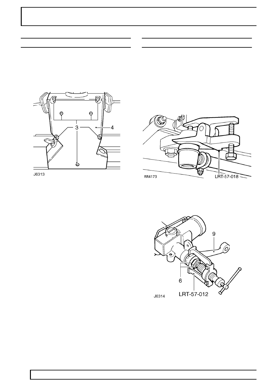
4. Disconnect drag link ball joint from drop arm
using extractor LRT-57-018.
5. Mark drop arm and steering box for reassembly.
6. Bend back tabs on locking washer, slacken
retaining nut, but do not remove.
7. Fit extractor LRT-57-012 and release drop arm
from steering box spline.
Нет комментариевНе стесняйтесь поделиться с нами вашим ценным мнением.
Текст