Defender 300Tdi (1996+). Manual — part 19
ENGINE
19
REPAIR
OIL FILTER
Service repair no - 12.60.01
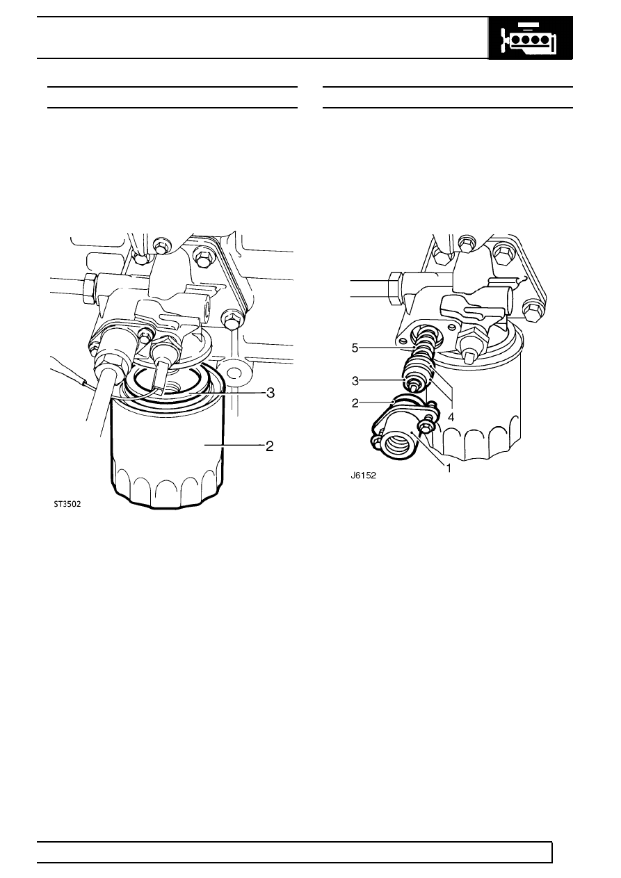
Remove
1. Place drain tray under oil filter.
2. Unscrew filter anti-clockwise, using a strap
wrench, if necessary.
Refit
3. Clean mating face of oil filter adaptor.
4. Coat rubber sealing ring of new filter with clean
engine oil.
5. Screw on filter until sealing ring touches
machined face, then tighten a further half turn by
hand only. DO NOT over tighten.
OIL TEMPERATURE CONTROL VALVE
Service repair no - 12.60.69
Remove
1. Clean adaptor housing.
2. Disconnect oil cooler feed pipe from thermostat
extension housing and plug to prevent ingress of
dirt.
3. Remove 2 bolts and carefully withdraw
thermostat extension housing (1) complete with
’O’ ring seal (2), thermostat (3), 2 washers (4)
and spring (5).
4. Inspect all parts and renew as necessary.
Refit
5. Fit thermostat to extension housing ensuring pin
locates in hole.
6. Fit two washers and spring to thermostat.
7. Fit a new ’O’ ring to extension housing.
8. Insert spring into adaptor and secure extension
housing to adaptor. Tighten bolts to
9 Nm (7
lbf/ft).
12
ENGINE
20
REPAIR
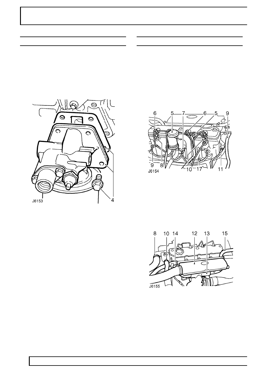
OIL FILTER HEAD GASKET
Service repair no - 12.60.03
Remove
1. Clean filter head adaptor.
2. Disconnect oil cooler pipes and plug to prevent
ingress of dirt.
3. Disconnect oil pressure switch lead.
4. Remove 4 bolts and withdraw filter head,
complete with gasket.
5. Clean mating faces of filter head and cylinder
block.
6. Fit head with new gasket.
7. Tighten bolts to
45 Nm (33 lbf/ft).
8. Reconnect oil pressure switch lead.
9. Reconnect oil cooler pipes.
CYLINDER HEAD GASKET
Service repair no - 12.29.02
Remove
1. Disconnect battery
2. Remove bonnet.
3. Drain coolant.
See COOLING SYSTEM,
Repair, Drain and refill cooling system
4. Remove air cleaner.
See FUEL SYSTEM,
Repair, Air cleaner
5. Detach crankcase ventilation valve and side
breather hose from rocker cover and move to
one side.
6. Remove fuel injectors and pipes.
See FUEL
SYSTEM, Repair, Fuel injectors
7. Remove heater plugs.
See FUEL SYSTEM,
Repair, Heater plugs
8. Disconnect radiator top hose from thermostat.
9. Disconnect bleed hose at thermostat.
10. Disconnect water pump hose at thermostat.
11. Disconnect water temperature sensor lead.
ENGINE
21
REPAIR
12. Remove induction manifold.
See MANIFOLD
AND EXHAUST SYSTEM, Repair, Induction
manifold
13. Remove exhaust manifold and turbocharger
assembly.
See MANIFOLD AND EXHAUST SYSTEM,
Repair, Exhaust manifold
14. Disconnect heater hose from water pump and
move heater rail aside.
15. Disconnect heater hose from rear of cylinder
head.
16. Remove bolt securing air cleaner mounting
bracket to support strut.
17. Remove bolt securing harness bracket to
cylinder head.
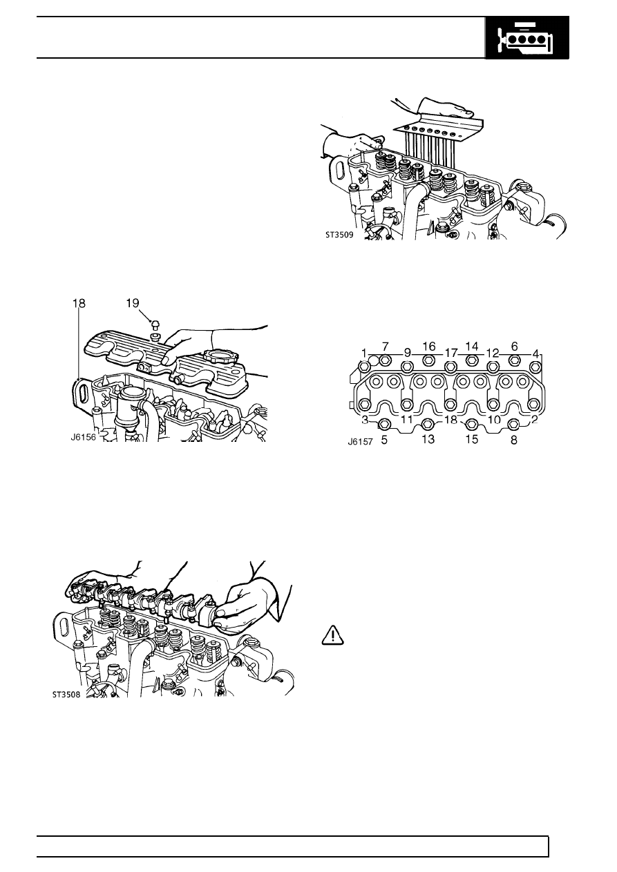
18. Remove rear engine lifting bracket. This will also
release clips securing transmission and engine
breather pipes and multi-plug. Note loose spacer
beneath inner clip.
19. Unscrew 3 bolts, with sealing washers and
remove rocker cover.
20. Remove 3 nuts and 2 bolts and lift rocker shaft
assembly from cylinder head.
21. Remove push rods and store as an identified set
to allow refitment to same location.
22. Remove valve stem caps.
23. Evenly slacken and then remove cylinder head
to block retaining bolts in the sequence shown in
J6157. Two of the bolts also secure the air
cleaner mounting bracket.
24. Lift off cylinder head and remove gasket.
Refit
25. Thoroughly clean mating faces of cylinder block
and head.
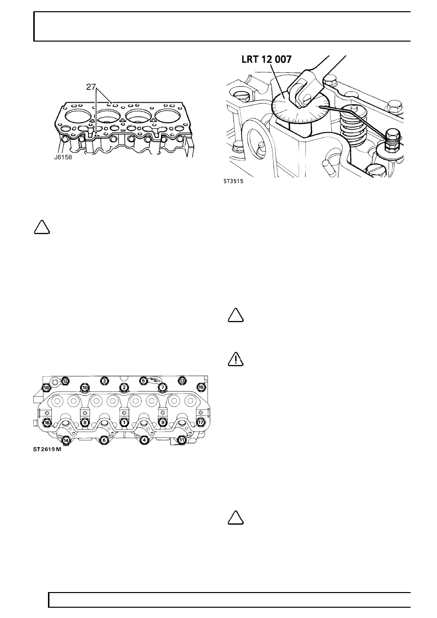
26. Select new gasket of correct thickness.
CAUTION: Three gaskets, of different
thicknesses, are available and can be
identified by the number of small holes
punched in the RH side of the gasket. One hole
identifies the thinnest gasket, two holes the
middle thickness and three holes the thickest.
When renewing a gasket it must be of the same
thickness as the one removed.
27. Position gasket on cylinder block with
identification holes on RH side and TOP
identification mark uppermost.
12
ENGINE
22
REPAIR
28. Lower cylinder head onto block ensuring correct
location with dowels.
NOTE: Cylinder head retaining bolts can
be used up to a maximum of five times.
29. Lubricate threads of bolts with light oil and fit to
positions shown below. (Fit air cleaner mounting
bracket at positions 6 and 14).
Bolt sizes:
M10 x 117mm locations 3, 5, 12, and 13.
M12 x 140mm locations 1, 2, 7, 8, 9, 10, 15, 16, 17,
and 18.
M12 x 100mm locations 4, 6, 11, 14.
30. Tighten bolts so that underside of heads just
make contact with cylinder head.
31. Following the sequence indicated, tighten all
bolts to
40 Nm (30 lbf/ft).
32. Attach angle gauge LRT-12-007.
33. Make a suitable pointer from welding rod and
attach to a bolt screwed into a rocker shaft
securing bolt hole.
34. Tighten all bolts through 60
°
strictly in sequence
illustrated.
35. Repeat 60
°
tightening procedure, again strictly in
sequence illustrated.
36. Tighten the 10 longer bolts (M12 x 140mm) a
further 20
°
, again following the sequence
illustrated.
NOTE: Repositioning of the pointer will be
necessary to reach all bolts, the pointer
can be fitted to the rocker shaft securing
studs using 2 nuts.
CAUTION: The double tightening
procedure MUST be carried out, on no
account should the bolt tightening be
performed in one operation, otherwise damage to
the cylinder head may occur.
37. Fit valve stem caps.
38. Fit push rods to locations from which they were
removed.
39. Position rocker shaft assembly over locating
studs and fit retaining nuts and bolts, but do not
tighten at this stage.
40. Attach angle gauge LRT-12-007.
41. Make a suitable pointer and attach to one of the
rocker shaft locating studs.
42. Tighten all fixings in turn to
5 Nm (4 lbf/ft). Then
tighten a further 50
°
in same sequence.
NOTE: Repositioning of the pointer will be
necessary to reach all fixings.
Нет комментариевНе стесняйтесь поделиться с нами вашим ценным мнением.
Текст