Defender 300Tdi (1996+). Manual — part 74
70
BRAKES
2
OVERHAUL
MASTER CYLINDER
Service repair no - 70.30.09
Before starting overhaul procedure refer to general
brake service practice
See Repair, General brake
service practice .
Dismantling master cylinder
1. Disconnect battery and remove master cylinder
from servo
See Repair, Master cylinder .
2. Before commencing overhaul procedure
thoroughly clean master cylinder and inspect
outer surfaces for damage and condition, renew
complete assembly if necessary.
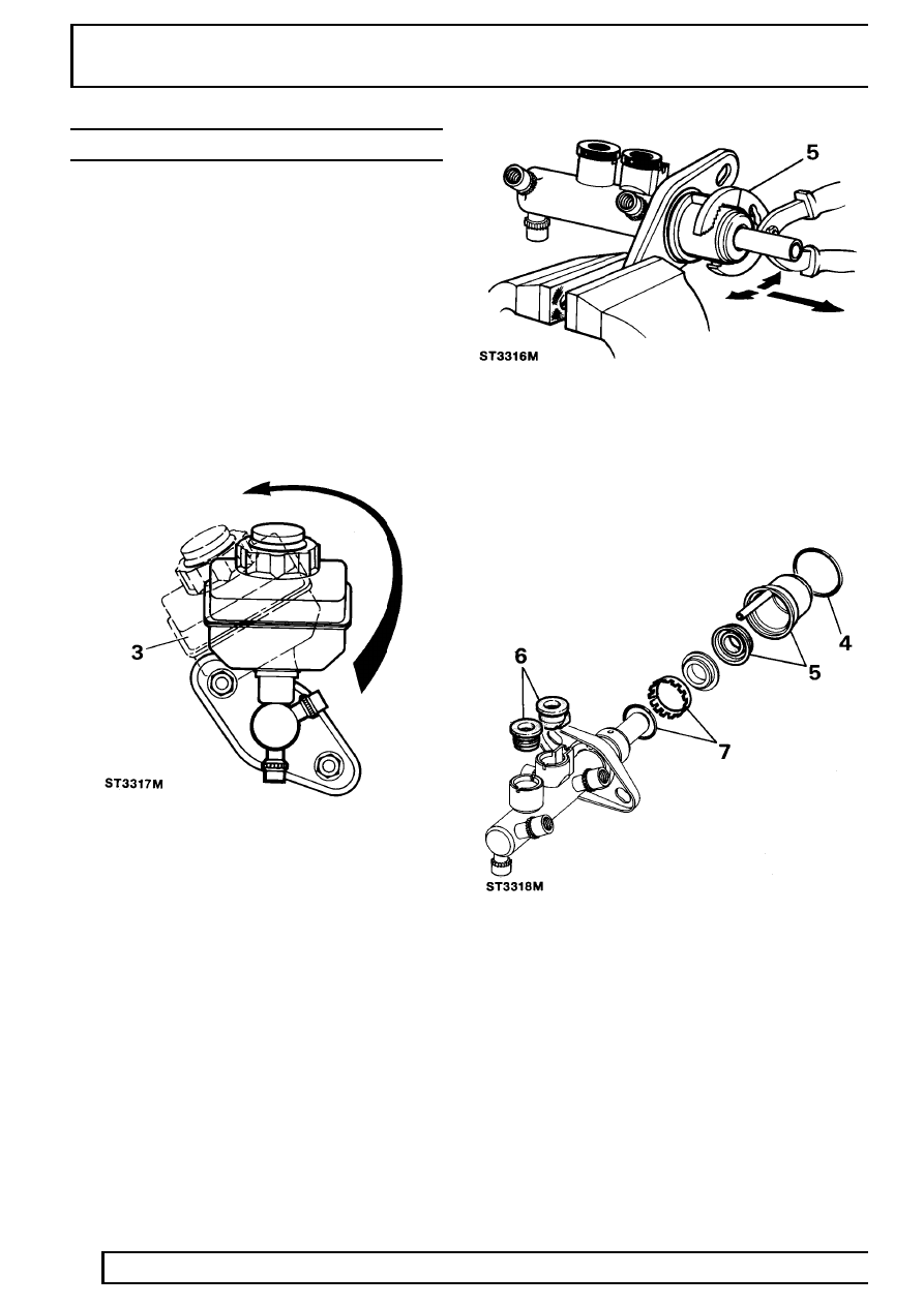
3. The reservoir is a push fit in master cylinder and
secured by seals. Carefully ease reservoir from
master cylinder by rolling it from seals as
illustrated.
4. Using soft jaws, one either side of master
cylinder flange and clamp flange in a suitable
vice. Remove water ingress ’O’ ring seal from
master cylinder to servo flange and discard.
5. Hold outside of transfer housing with a suitable
pair of grips, carefully pull, while working pliers in
a backwards and forwards rocking motion to
ease housing off master cylinder, discard
housing and vacuum seal.
6. Withdraw 2 reservoir seals from master cylinder
and note their positions in inlet ports for
reassembly. Discard both seals.
7. Remove retaining ring and ’O’ ring seal from
machined outer surface of master cylinder,
discard both seal and retaining ring.
BRAKES
3
OVERHAUL
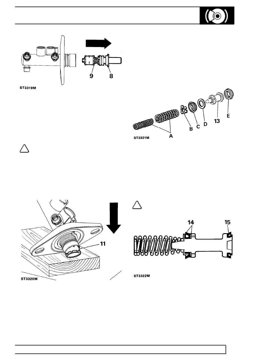
8. Remove guide ring from mouth of master
cylinder which supports primary plunger
assembly and place to one side, this component
is not part of master cylinder service kit and is to
be refitted on assembly of unit.
9. Pull primary plunger assembly out of master
cylinder.
NOTE: The primary plunger assembly
cannot be broken down any further and is
serviced as a complete unit. Discard
assembly.
10. The secondary plunger assembly will remain at
bottom of master cylinder bore, plunger can be
easily expelled by tapping assembly on a piece
of timber until plunger appears at cylinder mouth,
carefully pull plunger from master cylinder.
11. If swirl tube was not expelled at same time as
secondary plunger, repeat above operation to
expel it from bottom of master cylinder bore and
discard.
12. Clean all parts with Girling cleaning fluid or
unused brake fluid and place cleaned parts on to
a clean sheet of paper. Inspect cylinder bore and
plungers for signs of corrosion, ridges and score
marks. Provided working surfaces are in perfect
condition, new seals from a Girling Service
repair kit may be used.
Renewing secondary plunger seals
A. Springs
B. Seal retainer
C. Recuperating seal (primary cup)
D. Washer
E. ’L’ seal
13. Remove components above from secondary
plunger and discard:
NOTE: A small screwdriver with end
rounded and polished is required to
remove ’L’ seal. DO NOT damage
secondary plunger.
14. Coat new seals in unused brake fluid and firstly
fit ’L’ seal to plunger.
15. Fit washer followed by recuperating seal. Fit seal
retainer and springs, ensure springs are
correctly seated.
70
BRAKES
4
OVERHAUL
Assembling master cylinder
CAUTION: It is important that the following
instructions are carried out precisely,
otherwise damage could be caused to new
seals when inserting plungers into cylinder bore.
Generous amounts of new brake fluid should be
used to lubricate parts during assembly.
NOTE: Thoroughly check that no debris is
lodged in fluid passageways and drillings.
If debris is found, carefully remove,
re-clean cylinder and re-check.
16. Fit new swirl tube to bottom of cylinder bore.
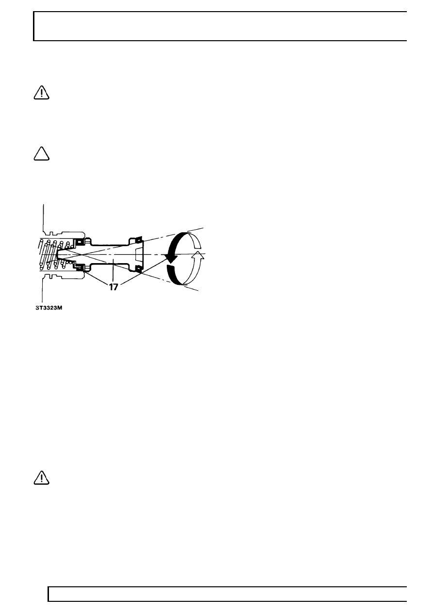
17. Lubricate secondary plunger and cylinder bore.
Offer plunger assembly to cylinder until
recuperation seal is resting centrally in mouth of
bore. Gently introduce plunger with a circular
rocking motion, as illustrated. Ensuring that seal
does not become trapped, ease seal into bore
and slowly push plunger down bore in one
continuous movement.
18. Fit primary plunger assembly using same
method as for secondary plunger, push plunger
down bore.
19. Fit original guide ring to support primary plunger.
20. Coat a new ’O’ ring with brake fluid and fit to its
respective groove on outer location surface of
master cylinder.
CAUTION: ’O’ ring should not be rolled
down outer location surface of master
cylinder but should be slightly stretched
and eased down cylinder and into its groove. Do
not over stretch seal.
21. Fit a new retaining ring on outer surface of
master cylinder ensuring that serrations of ring
are facing mounting flange.
22. Fit two new reservoir seals in their respective
ports.
23. Fit a new vacuum seal to either primary plunger
or to bottom of transfer housing bore, open face
of seal towards primary plunger guide ring.
24. Lubricate vacuum seal with brake fluid, fit
transfer housing to master cylinder, push
housing fully up to cylinder mounting flange. Do
not adjust transfer housing after fitting.
25. Lubricate a new water ingress seal with brake
fluid, slightly stretch seal and ease it down
housing until seal is in correct position between
housing and flange.
26. Roll reservoir into top of master cylinder,
reversing procedure described in instruction 3.
27. Fit master cylinder to servo
See Repair,
Master cylinder .
28. Reconnect battery, and road test vehicle.
WHEELS AND TYRES
1
DESCRIPTION AND OPERATION
TYPES OF WHEEL RIMS AND TYRES
Description
Dependent on specification and model type, the
vehicle is equipped with pressed steel or alloy wheel
rims, both using tubeless radial ply tyres.
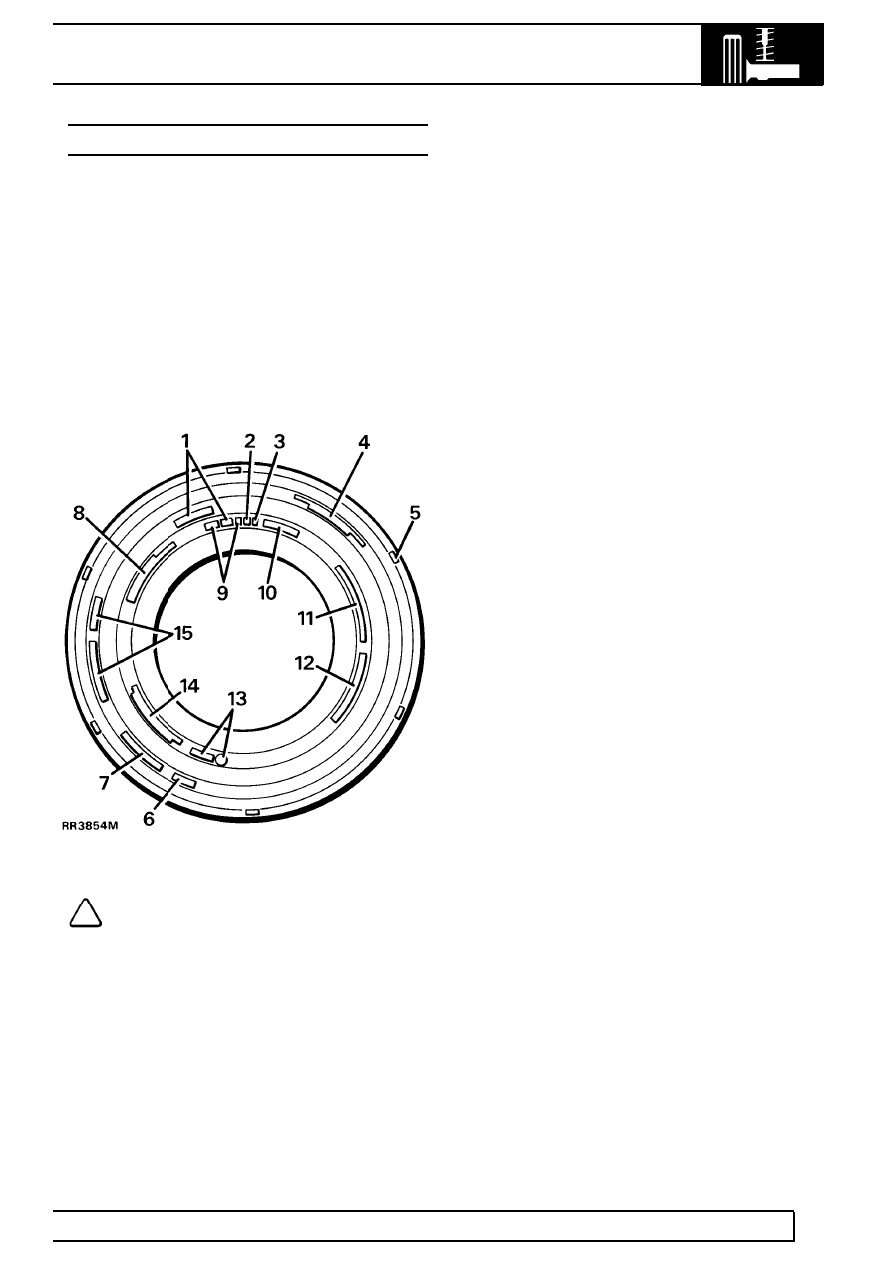
Tyre codes
The text, codes and numbers moulded into the tyre
wall vary between tyre manufacturers, however most
tyres are marked with the information shown in the
illustrated example.
NOTE: The illustration is an example of the
type of markings moulded into tyres and is
for guidance only. For specific tyre
specifications
See GENERAL SPECIFICATION
DATA, Information, Tyre size and pressures .
1. Type of tyre construction - Radial Ply
2. Load index - 104
3. Speed symbol - S or T
4. USA Tyre quality grading - Tread wear 160
Traction A temperature B
5. Tread wear indicators moulded into tread pattern
are located at intervals around the tyre and
marked by a code - E66 103S6
6. Tyres with ’Mud Snow’ type tread pattern are
marked - M&S
7. Tyre reinforcing mark - Reinforced
8. USA Load and pressure secification -
(900Kg(1984LBS) at 340KA (50PSI) MACS
PRESS
9. Tyre size - 205 16 ot 235/70 R16
10. Type of tyre - TUBELESS
11. Country of manufacture - MADE IN GREAT
BRITAIN
12. USA Compliance symbol and identification -
DOT AB7C DOFF 267
13. European type approval identification - E11
01234
14. Tyre construction - SIDE WALL 2 PLIES
RAYON. TREAD 2 RAYON 2 STEEL
15. Manufacturers brand name/type - TRACTION
PLUS mzx M
Нет комментариевНе стесняйтесь поделиться с нами вашим ценным мнением.
Текст