Defender 300Tdi (1996+). Manual — part 25
FUEL SYSTEM
5
ADJUSTMENT
Fuel injection pump
If the fuel injection pump has been removed or
renewed carry out the following:
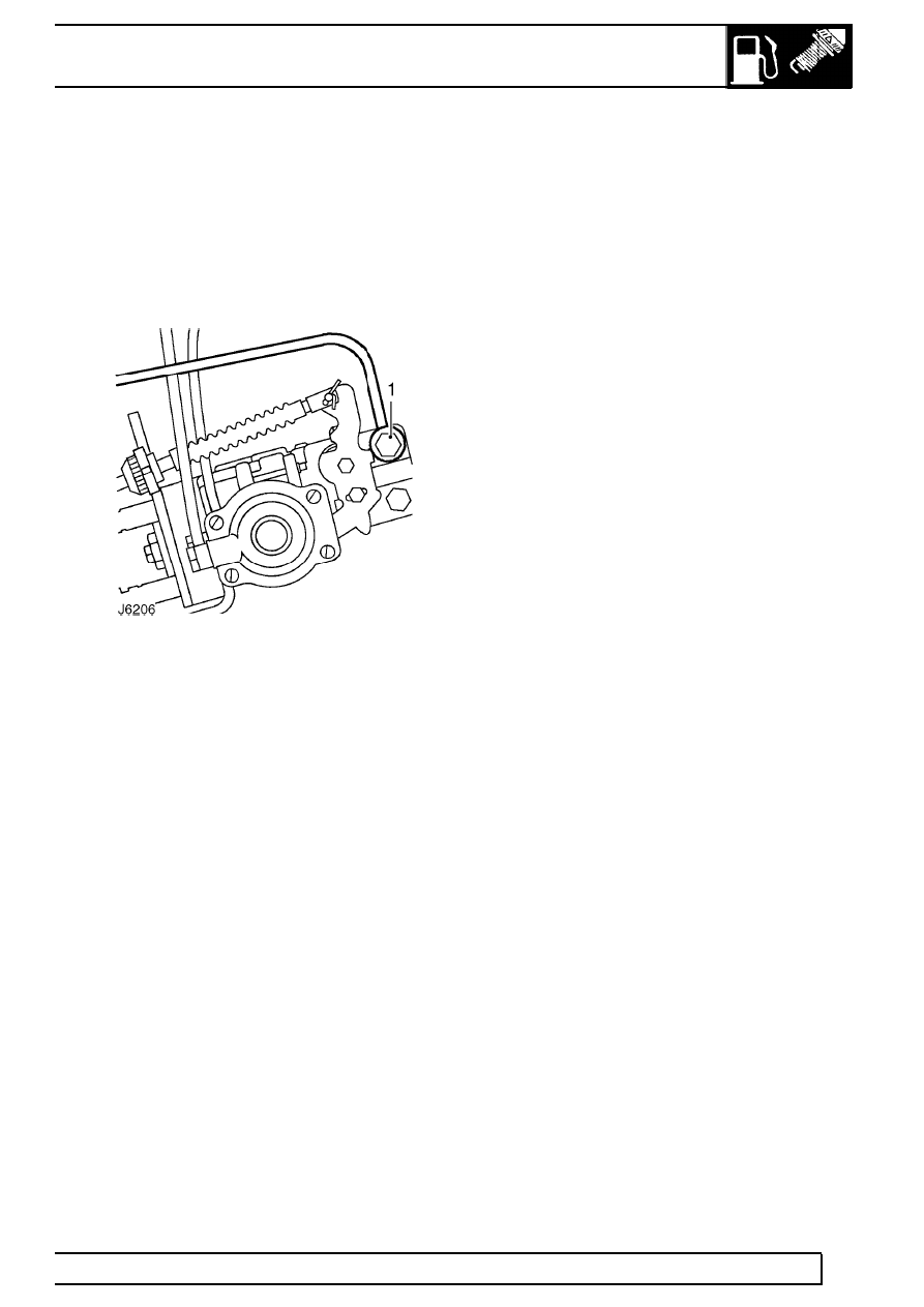
1. Slacken fuel inlet pipe banjo bolt at injection
pump.
2. Operate hand priming lever on fuel lift pump until
fuel, free from air, emerges from injection pump.
3. Tighten banjo bolt whilst fuel is still emerging.
4. Crank engine until fuel is drawn through the
system and engine starts.
5. Check fuel connections for leaks.
FUEL SYSTEM
1
REPAIR
FUEL INJECTION PUMP
Service repair no - 19.30.07
Remove
1. Disconnect battery.
2. Disconnect and remove high pressure fuel
injection pipes, pump to injectors.
3. Viewing valve mechanism through oil filler cap
aperture, turn crankshaft clockwise until No. 1
cylinder is just before TDC.
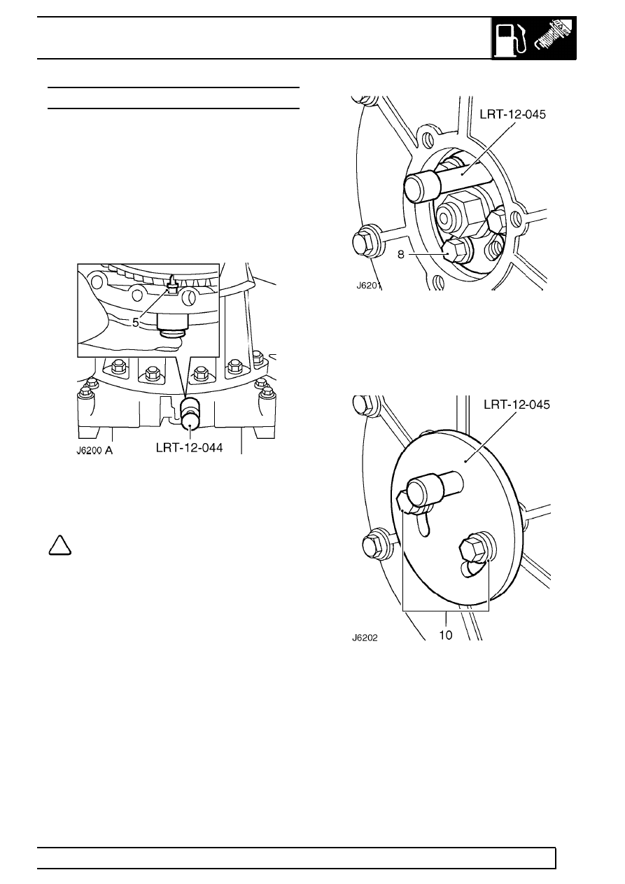
4. Remove blanking plug from flywheel housing
and fit timing tool LRT-12-044, locating centre
pin on flywheel.
NOTE: A chassis undertray may be fitted
on some vehicle derivatives to conform to
legal requirements. When under chassis
adjustments or remove and refit procedures are
required, it may be necessary to remove the
undertray and/or integral access panels
See
CHASSIS AND BODY, Repair, Front undertray or
See CHASSIS AND BODY, Repair, Rear undertray
5. Carefully rotate crankshaft clockwise until centre
pin engages with timing slot in flywheel.
6. Remove injection pump access plate, complete
with gasket, from front cover plate.
7. Fit pin from LRT-12-045 to injection pump gear.
8. Restrain pulley nut to prevent straining timing
belt and remove drive gear to pump hub fixing
bolts and retaining plate.
9. Remove pin from pump gear.
10. Fit gear retaining tool LRT-12-045 with an 8 mm
washer, 1,5 - 2 mm thick, under each bolt head
in addition to the existing washer.
11. Remove throttle cable and hand throttle cable, if
fitted.
12. Disconnect lead from fuel cut-off solenoid, and
EGR throttle position sensor multi-plug, if fitted.
19
FUEL SYSTEM
2
REPAIR
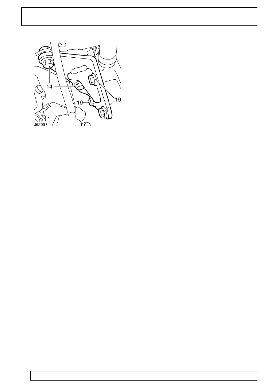
13. Remove banjo bolts securing spill return, main
fuel and boost signal pipes, refit banjo bolts after
disconnecting pipes.
14. Remove 2 bolts securing rear of pump to
mounting bracket.
15. Remove 3 pump securing nuts at flange and
withdraw pump and gasket.
16. Fit suitable caps to pipe connections to prevent
ingress of dirt.
Refit
17. Clean mating faces of pump and front cover and
fit new gasket into position over pump mounting
studs.
18. Remove pump blanking plugs.
19. Slacken the 3 bolts, securing injection pump
mounting bracket to cylinder block, sufficiently
enough to allow bracket to move.
20. Fit pump to cover and secure with 3 nuts.
Tighten to
25 Nm (18 lbf/ft).
21. Loosely attach pump to mounting bracket with
nuts and bolts, then tighten bolts securing
bracket to cylinder block and bolts securing
pump to bracket, finger tight only.
22. To ensure correct fitting and alignment of
injection pump, first tighten the 2 bolts securing
pump to mounting bracket to
25 Nm (18 lbf/ft).
Then tighten the 3 bolts securing mounting
bracket to cylinder block, also to
25 Nm (18
lbf/ft).
23. Connect spill return and main fuel pipes and
secure with banjo bolts. Tighten to
25 Nm (18
lbf/ft).
24. Connect boost signal pipe and secure with banjo
bolt. Tighten to
10 Nm (7 lbf/ft).
25. Connect fuel cut-off solenoid lead and throttle
position sensor multi-plug, if fitted.
26. Connect throttle cable and where applicable,
hand throttle cable.
27. Remove pump gear retaining tool LRT-12-045.
28. Carefully turn the pump hub nut in a clockwise
direction, sufficiently enough to enable timing
tool pin to be inserted into injection pump.
29. Fit gear retaining plate and secure with 3 bolts.
Tighten to
25 Nm (18 lbf/ft).
30. Remove timing pin.
31. Ensure flywheel timing pin is disengaged from
slot in flywheel.
32. Turn crankshaft two complete revolutions, check
timing pin from RT-12-045 can be fully and
easily inserted into the pump. At the same time
check flywheel timing pin LRT-12-044 can also
be inserted in the flywheel slot.
33. If, with the flywheel timing pin located, the timing
pin cannot be inserted cleanly into the injection
pump, carry out the following:
a. Ensure flywheel timing pin is disengaged from
slot in flywheel.
b. Slacken the 3 pump gear retaining bolts.
c. Turn the pump hub nut in a clockwise
direction, sufficiently to enable timing tool pin to
be easily inserted into the injection pump.
d. Keeping the tension on the hub nut, check
that flywheel timing pin locates with slot in
flywheel.
e. Tighten the 3 pump gear retaining bolts to
25
Nm (18 lbf/ft).
f. Remove timing pins from pump and flywheel
housing.
34. Using a suitable anti-seize compound, fit the
blanking plug to flywheel housing. Tighten to
12
Nm (9 lbf/ft).
35. Fit access plate with gasket to front cover plate.
Tighten bolts to
25 Nm (18 lbf/ft).
36. Refit injector pipes.
37. Reconnect battery.
FUEL SYSTEM
3
REPAIR
FUEL INJECTORS
Service repair no - 19.60.10
Remove
NOTE: When a fuel injector is considered
to be the cause of irregular running and
loss of power it will be necessary to fit a
donor set of injectors to determine which injector
is at fault. DO NOT attempt to dismantle or carry
out spray tests on the fuel injectors. This work
can only carried out by authorised Bosch dealers.
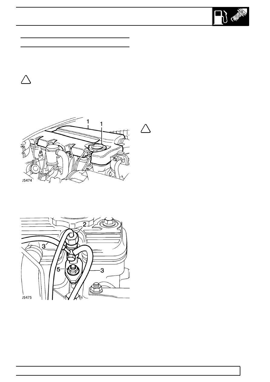
1. Remove oil filler cap and release sound
insulation cover from top of engine.
2. Disconnect high pressure fuel supply pipes from
injectors and injection pump. Remove in pairs.
3. Disconnect spill return hose(s) from injectors.
4. Plug pipes and injector connections to prevent
the ingress of dirt and foriegn matter.
5. Remove retaining nut and release each injector
clamp plate from cylinder head.
6. Remove injector and discard copper washer.
Refit
7. Ensure injectors and seating in cylinder head are
clean.
8. Lightly grease a new copper sealing washer and
position on each injector.
9. Fit injectors in cylinder head with spill return
outlets facing outward.
10. Secure injector with clamp plate and nut. Tighten
nut to
25 Nm (18 lbf/ft).
NOTE: The clamp plates are slightly
curved and should be fitted with the
convex side uppermost.
11. Fit the spill return pipe with a single copper
washer under the head of the banjo bolt and 2
copper washers fitted between the injector and
the banjo. Tighten banjo bolt to
10 Nm (7 lbf/ft).
12. Fit high pressure pipes to injectors and injection
pump. Tighten union nuts to
28 Nm (21 lbf/ft).
13. Fit sound insulation cover and oil filler cap.
Нет комментариевНе стесняйтесь поделиться с нами вашим ценным мнением.
Текст