Defender 300Tdi (1996+). Manual — part 58
57
STEERING
2
ADJUSTMENT
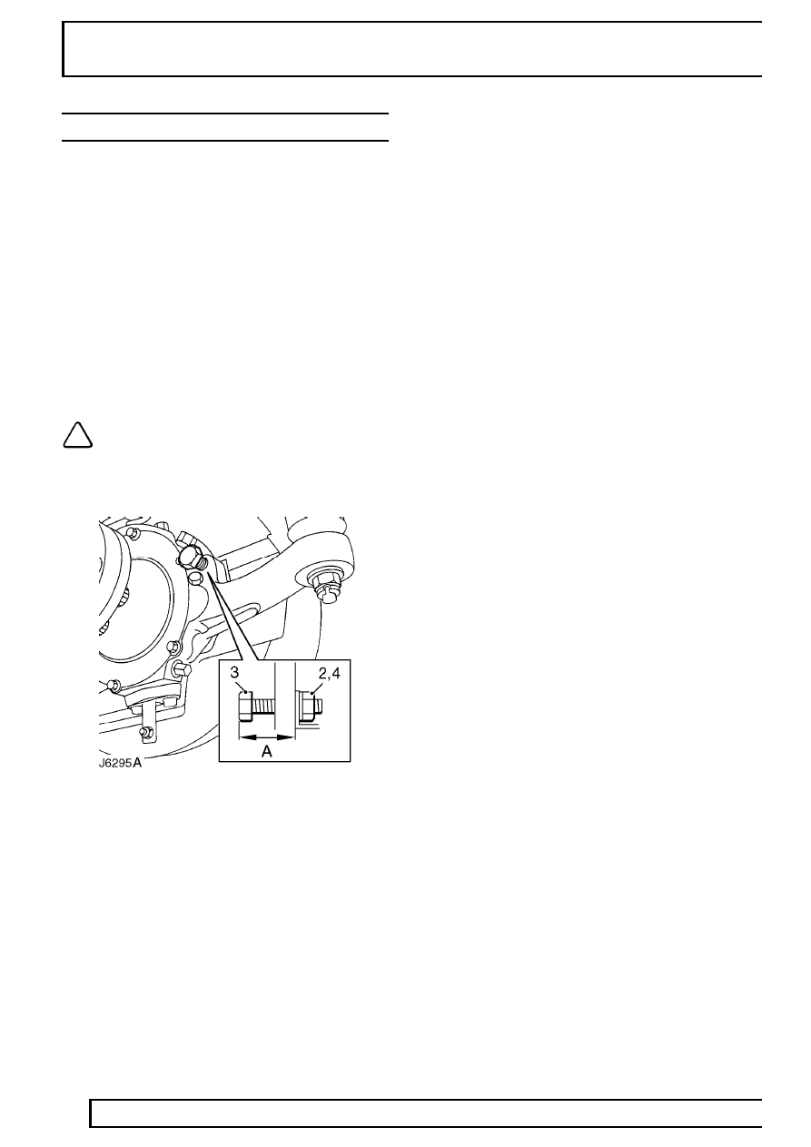
STEERING LOCK STOPS
Service repair no - 57.65.03
Check
1. Measure clearance between tyre wall and radius
arm at full lock. This must be not less than 20
mm.
Adjust
2. Loosen stop bolt locknut.
3. Turn stop bolt as required.
4. Tighten locknut.
5. Check clearance between tyre wall and radius
arm on each lock.
NOTE: Alternatively lock stop adjustment
may be carried out using following
procedure.
Check
1. Measure stop bolt protrusion ’A’. Refer to table
for correct setting.
Adjust
2. Loosen stop bolt locknut.
3. Turn stop bolt as required.
4. Tighten locknut.
5. Check wheel position at full lock.
LOCK STOP SETTINGS
Tyre & wheel size - alloys
Make
Size
Setting
BF Goodrich Mud Terrain
265
59,7 mm
Goodyear GT+4
235
55,7 mm
Michelin M+S 4x4
235
54,2 mm
Tyre & wheel size - steel
Make
Size
Setting
Goodyear
205
52,2 mm
Michelin
205
52,2 mm
Avon
7.50
56 mm
Michelin
7.50
56 mm
Goodyear
7.50
56 mm
STEERING
3
ADJUSTMENT
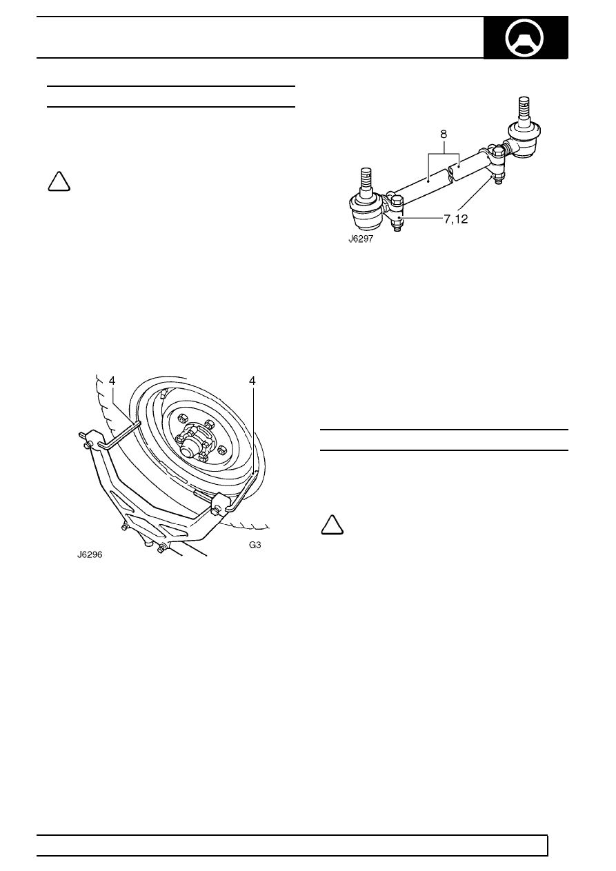
FRONT WHEEL ALIGNMENT
Service repair no - 57.65.01
Checking Toe-out dimensions
NOTE: Recognised front wheel alignment
and tracking equipment should be used
for this operation. Only the use of basic
equipment is described below. No Adjustment is
provided for castor, camber or swivel pin
inclinations.
1. Set vehicle on level ground with road wheels
positioned straight ahead.
2. Push vehicle back and forwards to settle linkage.
3. Set up the equipment to manufacturers
instructions and check alignment as advised by
equipment supplier.
4. Position trammel probes on inner face of wheel,
not the rims, if the latter are damaged.
5. Measure toe-out at horizontal centre-line of
wheels.
6. Check tightness of clamp bolt fixings. Tighten to
14 Nm (10lbf/ft).
Adjust
7. Slacken clamps at both ends of track rod.
8. Rotate track rod to increase or decrease its
effective length until correct toe-out is obtained
See GENERAL SPECIFICATION DATA,
Information, Steering .
9. Push vehicle rearwards turning steering wheel
from side to side to settle ball joints. With road
wheels set in straight ahead position, push
vehicle forward a short distance.
10. Recheck track and adjust if necessary.
11. When alignment is correct, tap ball joints in
direction of arrows to maximum of travel, to
ensure full unrestricted movement of track rod.
12. Tighten clamp bolts to
14 Nm (10 lbf/ft).
POWER STEERING PUMP DRIVE BELT
Service repair no - 57.20.01
Adjust
NOTE: For details of drive belt adjust
procedure.
See ELECTRICAL, Repair,
Auxiliary Drive Belt
STEERING
1
REPAIR
STEERING COLUMN
Service repair no - 57.40.01
Remove
1. Remove bonnet.
2. Set road wheels and steering wheel in straight
ahead position.
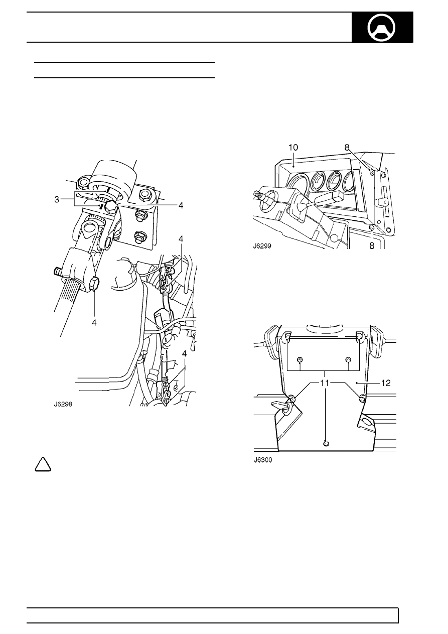
3. Mark relationship of steering column inner shaft
to top universal joint.
NOTE: collapsible shaft can be
disconnected from steering column only, if
required, by removing bolts from top
universal joint and slackening top bolt of lower
universal joint.
4. Remove 2 bolts from top universal joint and
lower bolt of bottom universal joint. Slacken top
bolt of lower universal joint and withdraw shaft.
5. Prise centre cap from steering wheel.
6. Remove steering wheel retaining nut and
withdraw wheel from column spline.
7. Disconnect battery.
8. Remove 4 screws securing instrument panel and
pull panel away from facia to enable
speedometer cable to be disconnected.
9. Disconnect multi-plugs, electrical leads and
connections to vehicle alarm system, if fitted.
See ELECTRICAL, Repair, Vehicle
immobilisation and alarm system .
10. Withdraw panel complete with instruments.
11. Remove 5 screws and 2 self-tapping screws to
remove top half of nacelle.
12. Ease bottom half of nacelle from switch
gaiters/grommets and remove.
57
STEERING
2
REPAIR
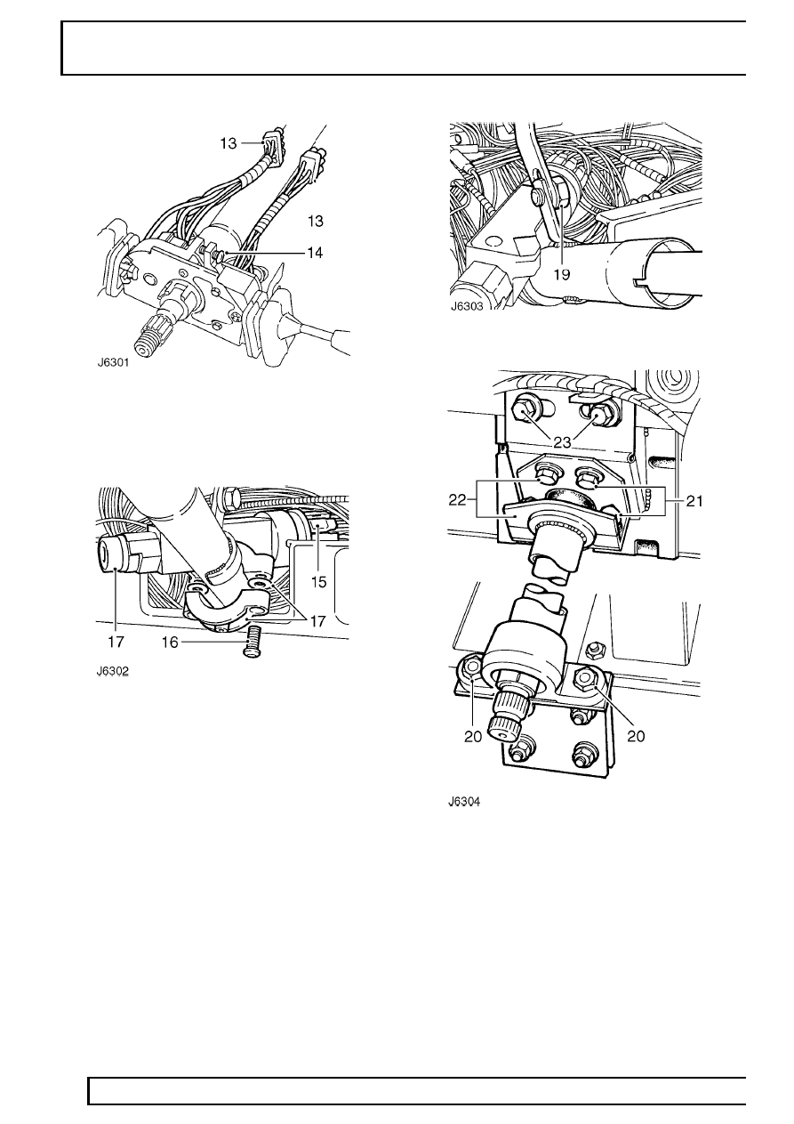
13. Disconnect 3 switch multi-plugs.
14. Slacken clamp screw on top of switch cluster
and withdraw switch assembly.
15. Note position of harness leads on back of starter
switch and disconnect lucars. If fitted, remove
alarm system passive coil from switch
See
ELECTRICAL, Repair, Vehicle immobilisation
and alarm system .
16. Using a punch or stud extractor remove 2 shear
bolts securing switch to column.
17. Remove switch and collect 2 plain washers
between switch and clamp.
18. Remove brake pedal box
See BRAKES,
Repair, Brake pedal .
19. Remove bolt securing tie-bar to steering column,
behind instrument panel.
20. Remove 2 bolts securing column lower support
to mounting bracket.
21. Remove bolts securing two halves of top clamp
and bolts that secure top half of clamp to
bulkhead.
22. Remove clamp and rubber packing.
23. Remove 2 bolts securing column main support
bracket to bulkhead.
24. Remove steering column and main support
bracket from vehicle.
Нет комментариевНе стесняйтесь поделиться с нами вашим ценным мнением.
Текст