Defender 300Tdi (1996+). Manual — part 108
86
ELECTRICAL
12
REPAIR
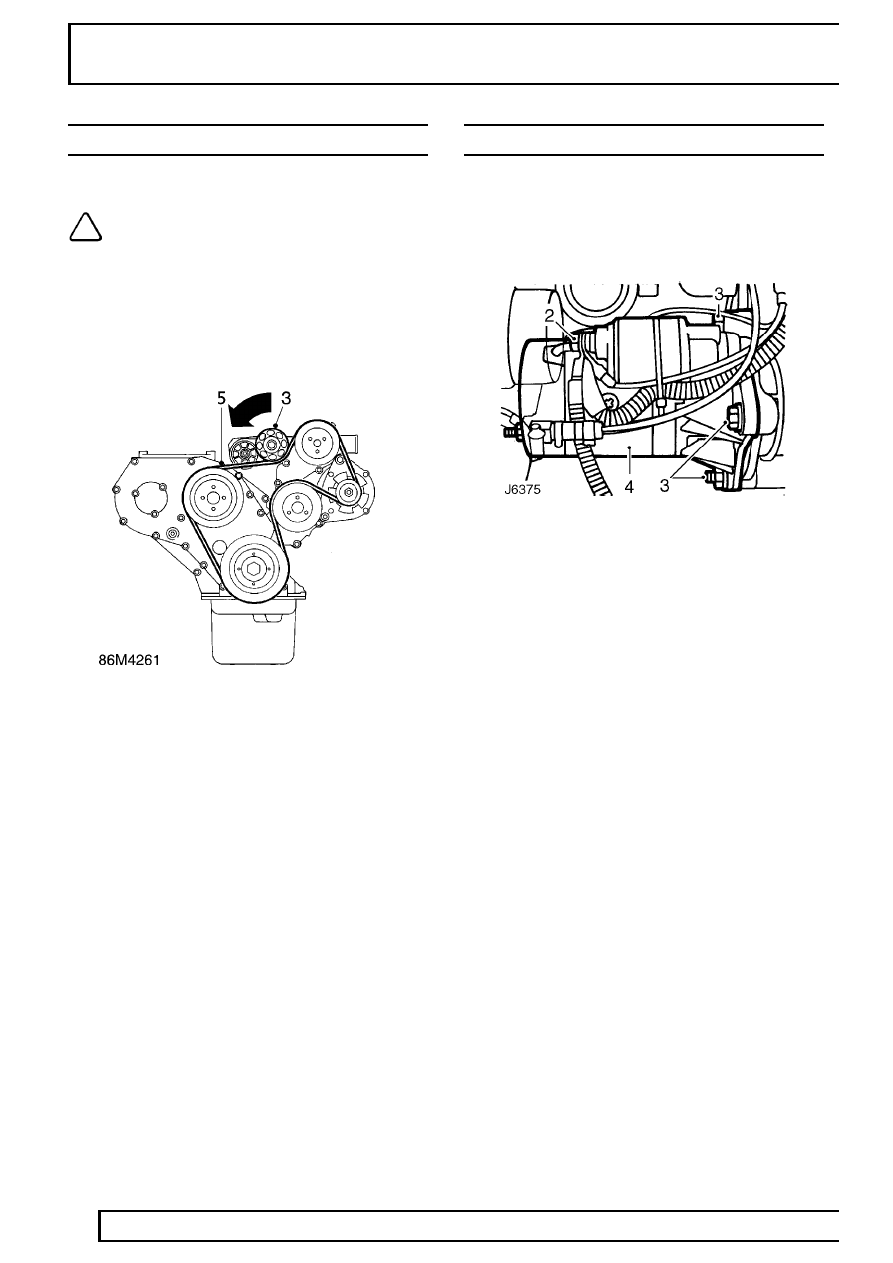
AUXILIARY DRIVE BELT
Service repair no - 86.10.03
NOTE: If cast lines on tensioner arm and
tensioner spring case are aligned, a new
drive belt must be fitted.
Remove
1. Disconnect battery.
2. Remove fan cowl
See COOLING SYSTEM,
Repair, Fan cowl.
3. Apply ring spanner to tensioner pulley retaining
bolt.
4. Turn spanner to release pulley tension from belt.
5. Detach belt from pulley.
6. Release tensioner.
7. Complete removal of belt. Mark direction on belt
if refitting.
Refit
8. Using ring spanner, release pulley tensioner and
fit new drive belt.
9. Remove ring spanner, drive belt will
automatically tension.
10. Fit fan cowl
See COOLING SYSTEM, Repair,
Fan cowl.
STARTER MOTOR
Service repair no - 86.60.01
Remove
1. Disconnect battery.
2. Disconnect electrical leads from starter solenoid.
3. Remove 3 fixings securing starter motor to
flywheel housing.
4. Withdraw starter motor.
Refit
5. Locate starter motor and secure to flywheel
housing.
6. Reconnect electrical leads to starter solenoid.
7. Reconnect battery.
ELECTRICAL
13
REPAIR
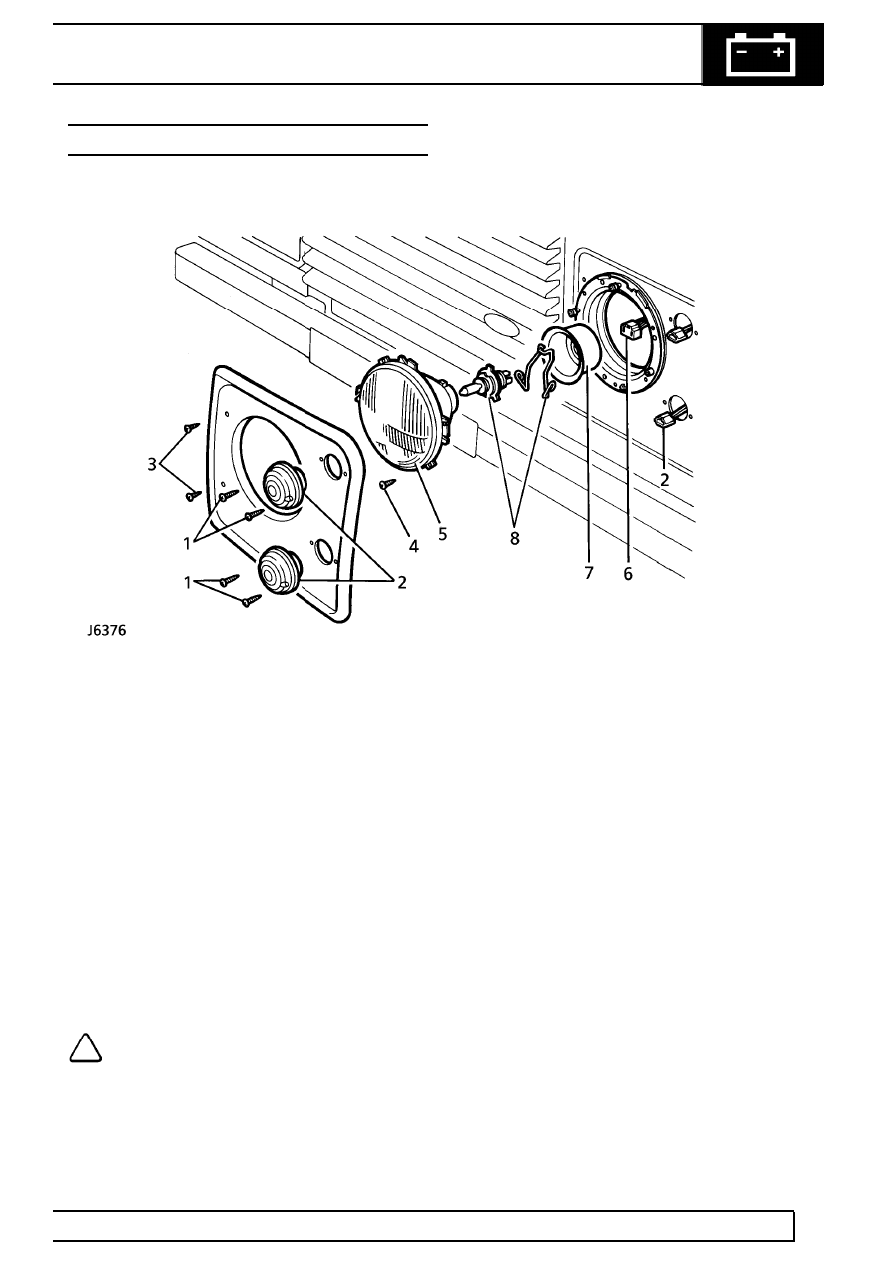
HEADLAMP
Service repair no - 86.40.02
Remove
1. Remove screws retaining side and direction
indicator lamps.
2. Withdraw lamp units and disconnect plugs.
3. Remove 2 screws and withdraw headlamp
finisher.
4. Remove 2 headlamp retaining screws.
5. Rotate headlamp clockwise, disengage from
body, and lift out headlamp.
6. Disconnect multi-plug to release headlamp. On
vehicles fitted with headlamp levelling unit, also
release unit harness plug
See Headlamp
levelling unit.
7. Remove rubber cover.
8. Release spring clip and withdraw headlamp
bulb.
NOTE: Do not touch bulb glass with
fingers. If necessary, clean bulb with
methylated spirits.
Refit
9. Fit bulb to headlamp and retain with spring clip.
10. Fit rubber cover and reconnect multi-plug. If
applicable, fit headlamp levelling unit plug
See
Headlamp levelling unit.
11. Locate headlamp in body and rotate
anti-clockwise to engage.
12. Fit headlamp retaining screws.
13. Fit headlamp finisher, side and direction
indicator lamps.
14. Check main beam alignment
See Headlamp
beam alignment.
86
ELECTRICAL
14
REPAIR
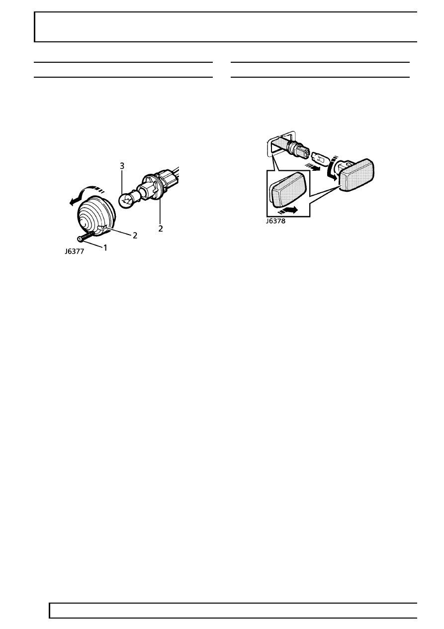
SIDE, TAIL AND DIRECTION INDICATOR LAMPS
Service repair no - 86.40.34 - Front side lamp
Service repair no - 86.40.45 - Tail lamp
Service repair no - 86.40.42 - Front direction
indicator lamp
Service repair no - 86.40.43 - Rear direction
indicator lamp
Remove
1. Remove 2 screws and withdraw lamp unit.
2. Hold bulb holder and twist lens to release.
3. Push and twist bulb to remove from holder.
Refit
4. Fit new bulb, if necessary.
5. Fit bulb holder to lamp lens.
6. Secure lamp to vehicle.
SIDE REPEATER LAMP
Service repair no - 86.40.53.
Remove
1. Push lens firmly to the right.
2. Lift left edge and withdraw lamp unit from wing.
3. Twist bulb holder and release from lens.
4. Pull bulb from holder.
Refit
5. Fit new bulb, if necessary.
6. Fit bulb holder to lens.
7. Locate lamp unit in wing and push firmly to the
left to secure.
ELECTRICAL
15
REPAIR
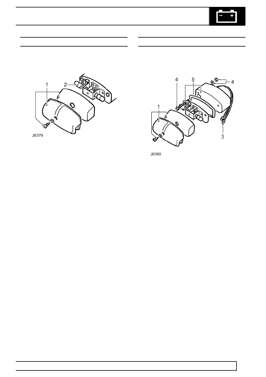
REAR NUMBER PLATE LAMP - BULB RENEWAL
Service repair no - 86.40.85
Remove
1. Remove single screw securing lamp cover and
lens to bulb holder.
2. Remove bulb/s from holder.
Refit
3. Fit new bulb/s.
4. Fit lamp lens and cover.
REAR NUMBER PLATE LAMP
Service repair no - 86.40.86
Remove
1. Remove single screw and remove lamp cover
and lens.
2. Uncsrew 2 fixings and remove metal cover to
gain access to lamp fixings and harness leads
inside vehicle.
3. Disconnect lamp leads from harness.
4. Remove 2 bolts, nuts and washers securing
lamp to vehicle body.
5. Remove bulb holder, complete with rubber seal
and mounting plinth.
Refit
6. Feed lamp unit leads through vehicle body and
secure bulb holder, seal and plinth.
7. Fit lamp leads to harness connectors.
8. Fit cover to conceal lamp fixings.
9. Fit lens and lamp cover.
Нет комментариевНе стесняйтесь поделиться с нами вашим ценным мнением.
Текст