Defender 300Tdi (1996+). Manual — part 46
51
REAR AXLE AND FINAL DRIVE
6
REPAIR
REV: 09/97
Refit
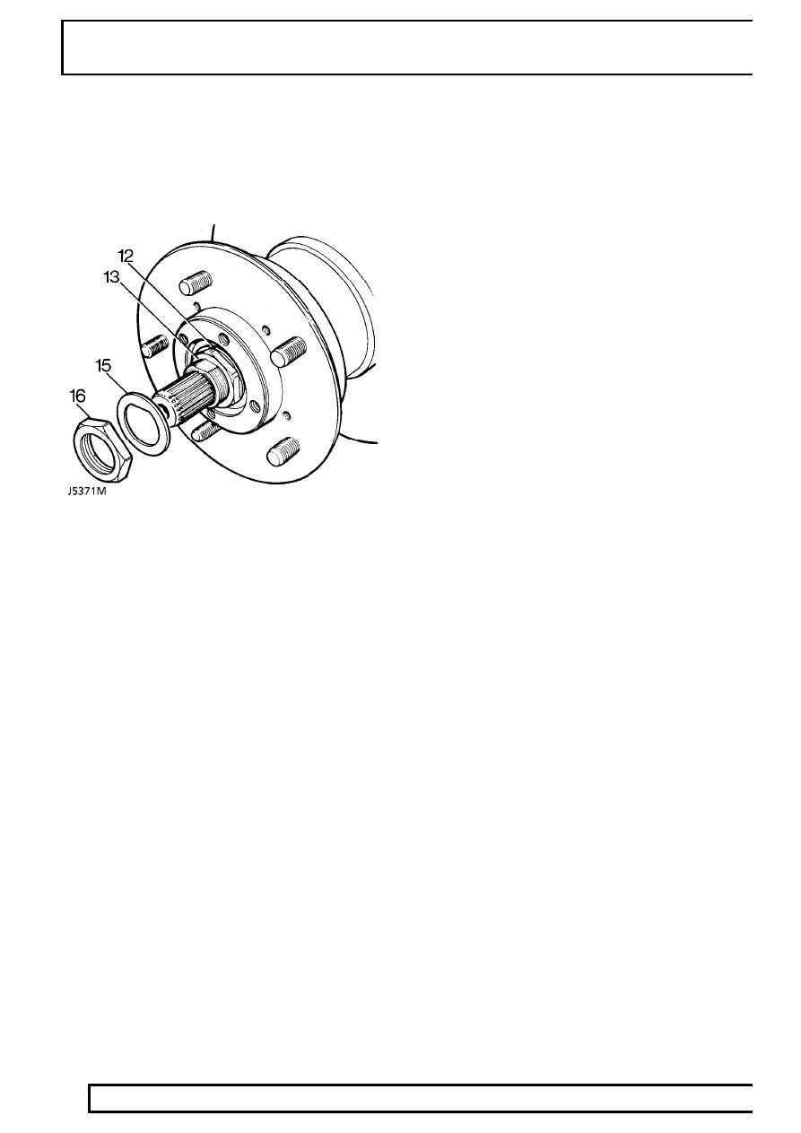
11. Clean stub axle and drive shaft and fit hub
assembly to axle.
12. Fit spacing washer.
13. Fit hub adjusting nut. Tighten to
50 Nm (37
lbf/ft) . Ensure hub is free to rotate with no
bearing play.
14. Back off adjusting nut 90
°
and tighten to
10 Nm
(7 lbf/ft).
15. Fit a new lock washer.
16. Fit locknut. Tighten to
50 Nm (37 lbf/ft).
17. Tab over lock washer to secure adjusting nut
and locknut.
18. Fit a new joint washer to driving member and fit
member to hub. Tighten bolts to
65 Nm (48
lbf/ft).
19. Fit circlip and dust cap.
20. Fit brake disc shield and brake caliper. Tighten
bolts to
82 Nm (61 lbf/ft).
21. Bleed brake system
See BRAKES, Repair,
Brake system bleed .
22. Fit road wheel, remove axle stands and tighten
road wheel nuts to correct torque:
Alloy wheels -
130 Nm (96 lbf/ft)
Steel wheels -
100 Nm (80 lbf/ft)
Heavy duty wheels -
170 Nm (125 lbf/ft)
23. Operate footbrake to locate brake pads before
driving vehicle.
REAR AXLE AND FINAL DRIVE
7
REPAIR
DIFFERENTIAL ASSEMBLY - 90
Service repair no - 51.15.01
Remove
1. Using suitable container, drain axle oil.
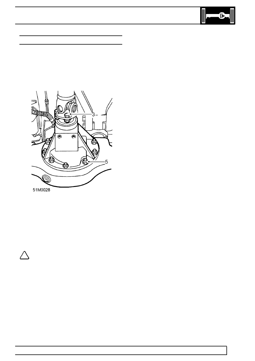
2. Mark differential and propeller shaft flanges to
facilitate reassembly.
3. Remove 4 bolts and disconnect propeller shaft
from differential. Tie aside.
4. Remove 5 hub drive member bolts and withdraw
axle half shafts sufficiently to disengage from
differential unit.
5. Remove 10 nuts securing differential to axle
case.
6. Withdraw differential unit.
NOTE: The differential unit can only be
serviced as a complete assembly with
matching drive pinion. For advice ring
Land Rover Service Department.
Refit
7. Ensure mating faces are clean and apply a bead
of RTV sealant to axle case.
8. Support differential unit and position on axle
casing.
9. Secure with self locking nuts and tighten to
40
Nm (30lbf/ft).
10. Align marks on flanges and secure propeller
shaft to differential. Tighten bolts to
48 Nm (35
lbf/ft).
11. Refit half shafts, using new drive member
gaskets. Tighten bolts to
65 Nm (48 lbf/ft).
12. Refill axle oil with approved lubricant
See
LUBRICANTS, FLUIDS AND CAPACITIES,
Information, Recommended lubricants and
fluids .
REAR AXLE AND FINAL DRIVE
1
OVERHAUL
DIFFERENTIAL ASSEMBLY - 110/130
Service repair no - 51.15.07
Overhaul
1. Drain off differential lubricating oil, and refit plug.
2. Remove rear axle assembly from vehicle
See
Repair, Rear axle
3. Remove hub driving member fixings.
4. Withdraw driving member and axle shaft
sufficiently to disengage differential.
5. Repeat instruction 4 for other axle shaft.
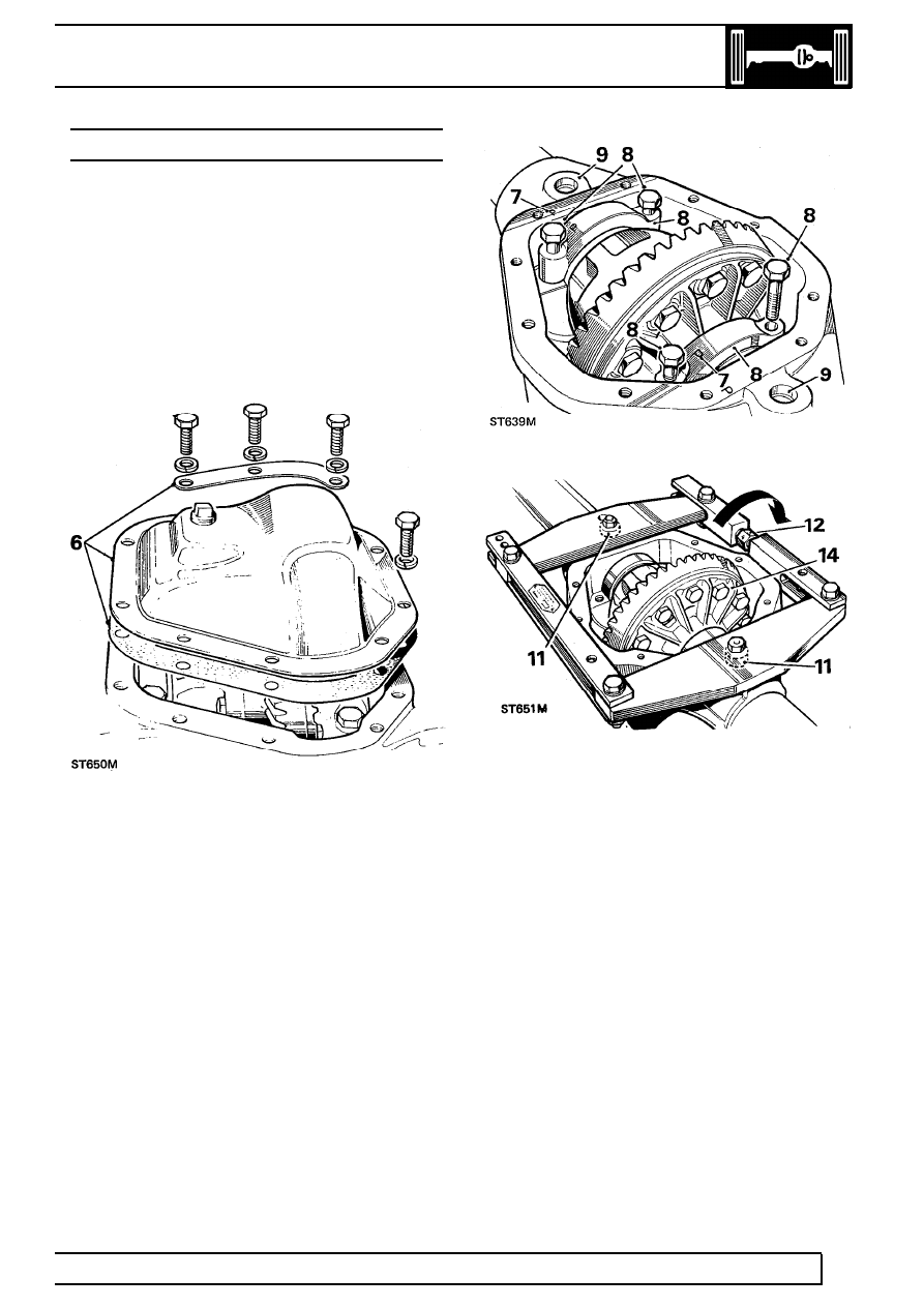
6. Remove fixings and support strip at differential
cover and withdraw cover and joint washer.
7. Note relationship marking on bearing caps and
axle casing to ensure correct refitting.
8. Remove fixings and withdraw differential bearing
caps.
9. Clean out and examine spreader tool pegholes
provided in gear casing face; ensure that holes
are free from dirt and burrs and damage.
10. Ensure that turnbuckle adjuster is free to turn.
Using axle spreader 18G31C
11. Fit axle spreader to engage peg holes.
(Spreader 18G131C, Adaptor pegs 18G131F)
12. Using a spanner, turn adjuster until all free play
between spreader and casing is taken up,
denoted by adjuster becoming stiff to turn.
13. Check that side members of spreader are clear
of casing.
14. Stretch casing, rotating adjuster by one flat at a
time, until differential assembly can be levered
out. Do not lever against spreader; use suitable
packing under levers to avoid damage to casing.
51
REAR AXLE AND FINAL DRIVE
2
OVERHAUL
CAUTION: To prevent permanent damage
to the gear carrier case, it must not be
over-stretched. Each flat on the turnbuckle
is numbered to enable a check to be made on the
amount turned. The maximum stretch permitted is
0,30 mm, equivalent to three flats.
15. Ease off adjuster and remove spreader.
Using axle compressor LRT-51-503 (GKN 131)
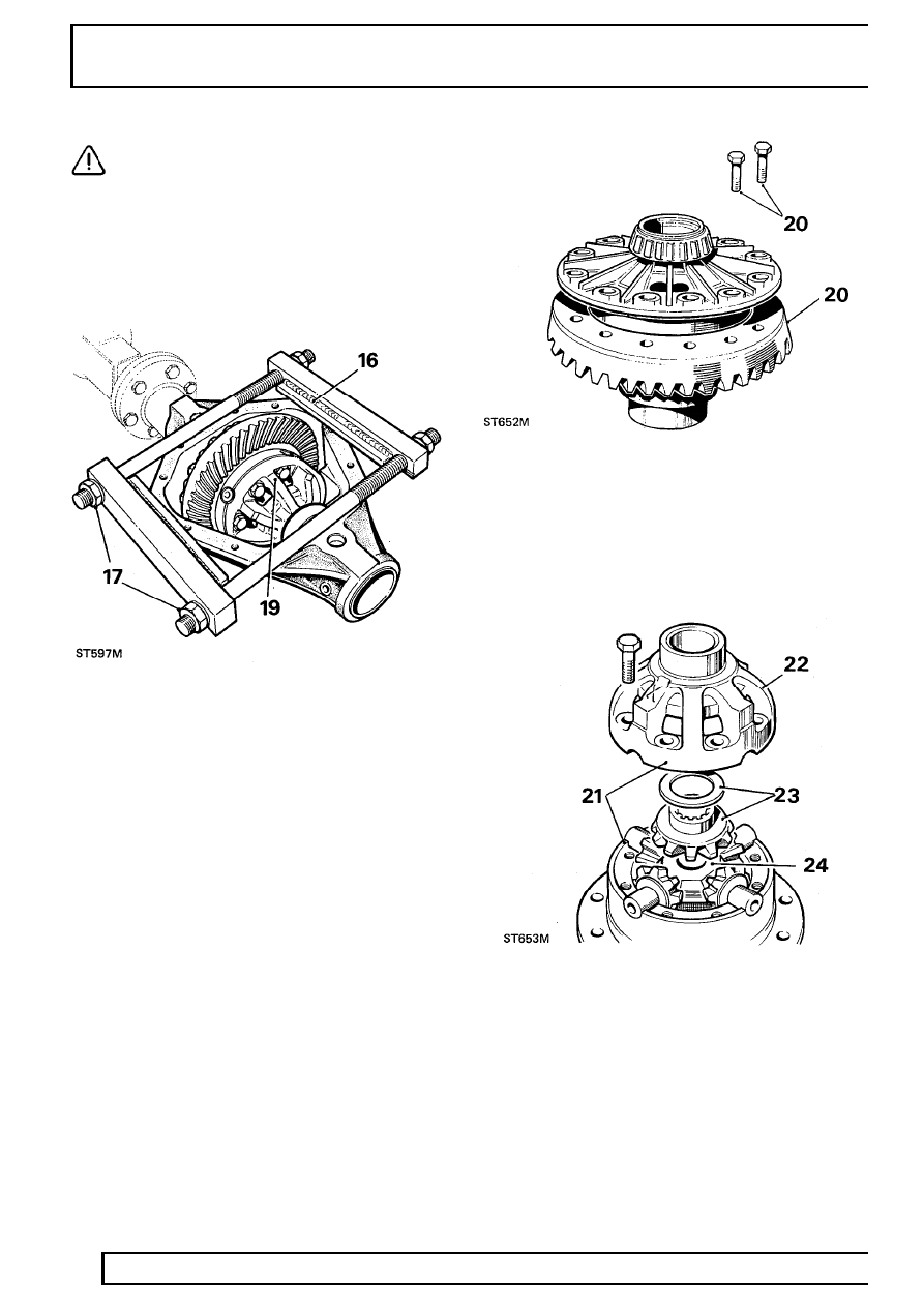
16. Place tool on to differential casing, as illustrated,
with weld seam uppermost. Ensure that plates
rest squarely on differential machined surface
and end bars butt against edges of casing.
17. Tighten adjusting nuts by hand only, until all
slack is taken up.
18. Continue to tighten both nuts alternately with a
spanner, one flat at a time, to a maximum of
three flats.
19. Carefully lever-out differential assembly.
Dismantle differential
20. Add alignment marks between crown wheel and
differential case for reassembly purposes, then
remove fixings and withdraw crown wheel.
21. Note alignment markings on two differential
casings to ensure correct refitting, then remove
fixings.
22. Lift off upper case.
23. Withdraw upper differential wheel and thrust
washer.
24. Lift out cross-shaft and pinions.
Нет комментариевНе стесняйтесь поделиться с нами вашим ценным мнением.
Текст