Defender 300Tdi (1996+). Manual — part 111
86
ELECTRICAL
24
REPAIR
HEADLAMP BEAM ALIGNMENT
Service repair no - 86.40.17
Check
Check main beam alignment using beam setting
equipment. Should this not be available the beam can
be temporarily checked and adjusted as follows:-
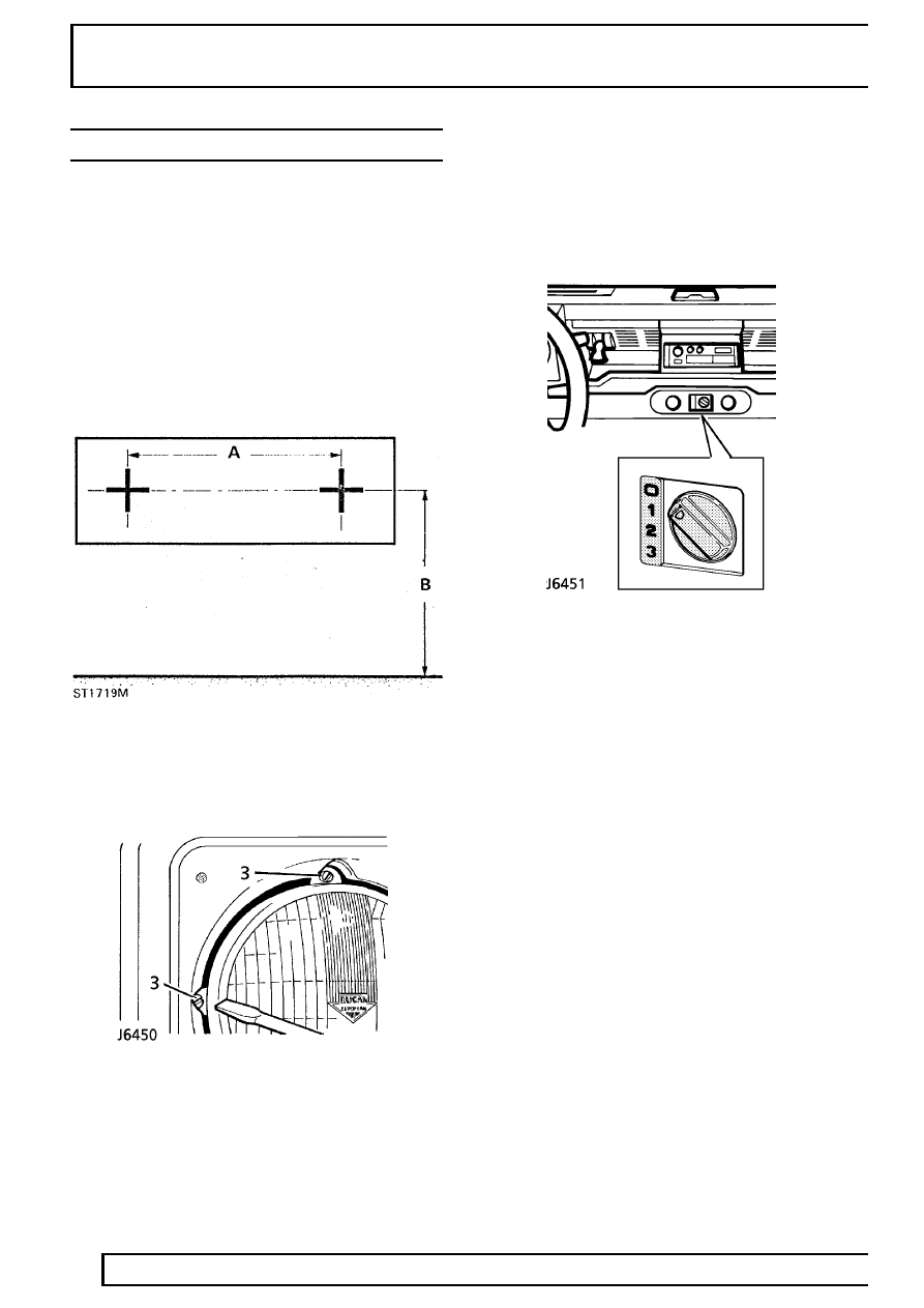
1. Position vehicle, unladen, on level ground with
tyres correctly inflated, approximately 4 meters
from a wall or screen, marked as illustrated
below.
2. The beam centres ’A’ are measured horizontally
on the vehicle and dimension ’B’ vertically from
the ground.
3. Switch on main beam and adjust setting, as
necessary, with trimmer screws.
On vehicles fitted with headlamp levelling units, check
and adjust headlamp beam alignment as previously
described, with fascia mounted levelling switch at
position ’0’. The headlamps can then be adjusted,
according to load conditions, as follows:-
Position ’0’ - Driver only, or driver and all front seats
occupied (loadspace empty).
Position ’1’ - All seats occupied (loadspace empty).
Position ’2’ - All seats occupied by adults and
loadspace loaded to maximum rear axle weight.
Position ’3’ - Driver only with loadspace loaded to
maximum rear axle weight.
ELECTRICAL
25
REPAIR
DIGITAL DIESEL SHUT-OFF VALVE (DDS)
Service repair no - 86.77.00
Remove
1. Remove fuel injection pump
See FUEL
SYSTEM, Repair, Fuel injection pump.
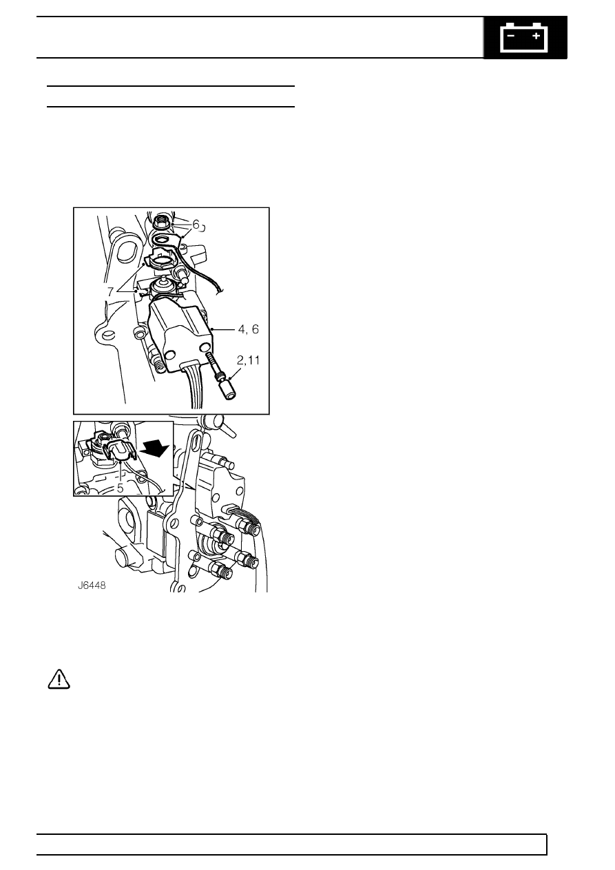
2. Drill out 2 shear bolts securing DDS valve and
clamp, using a 3.2 mm drill, to a depth of
approximately 5 mm.
CAUTION: Use a drill bushing to guide the
drill.
3. Using an extractor, remove the 2 DDS valve
retaining bolts and discard.
4. Release DDS valve from fuel shut-off solenoid.
5. Remove protective cap from shut-off solenoid.
6. Unscrew terminal nut, release terminal lead
eyelet and remove DDS valve.
7. Remove protective cap retainer and release
DDS valve clamp from behind fuel shut-off
solenoid.
Refit
8. Position DDS valve clamp behind fuel shut-off
solenoid and fit protective cap retainer.
9. Fit DDS terminal lead to fuel shut-off solenoid.
Tighten nut to
2 Nm (1.5 lbf/ft).
10. Fit protective cap to fuel shut-off solenoid,
ensuring terminal lead is correcly routed on RH
side of cap.
11. Secure DDS valve to fuel cut-off solenoid and
clamp. Tighten new shear bolts progressively
until heads shear.
12. Fit fuel injection pump
See FUEL SYSTEM,
Repair, Fuel injection pump.
INSTRUMENTS
1
REPAIR
INSTRUMENT PANEL
Service repair no - 88.20.02
Remove
1. Disconnect battery.
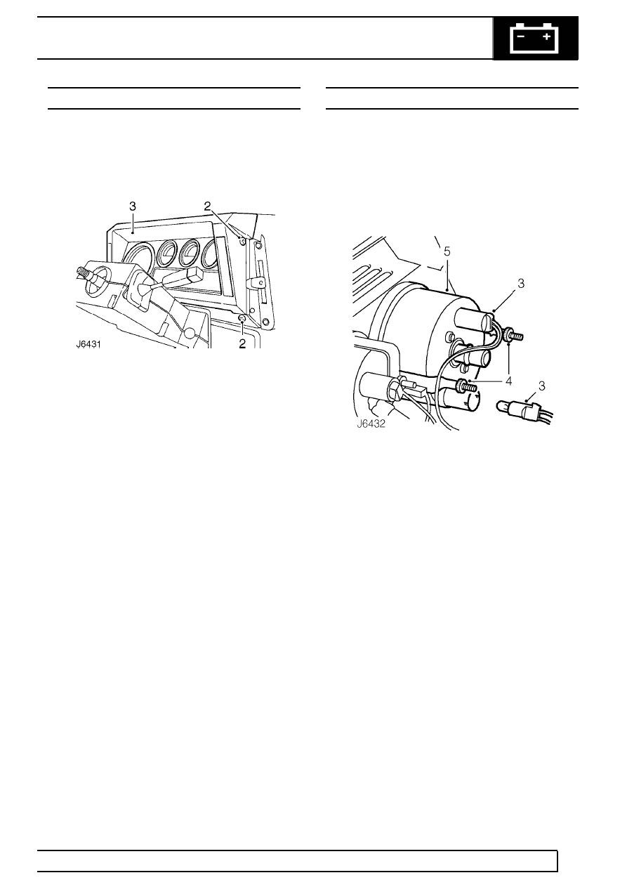
2. Remove 4 screws securing instrument panel to
fascia cowl.
3. Pull instrument panel away from fascia sufficent
to disconnect speedometer cable.
4. Disconnect multi-plugs, electrical leads and
connections to vehicle alarm system, if fitted
See ELECTRICAL, Repair, Vehicle
immobilisation and alarm system .
5. Withdraw panel, complete with instruments.
Refit
6. Offer up instrument panel, connect multi-plugs,
electrical leads and connections to vehicle alarm
system, if fitted
See ELECTRICAL, Repair,
Vehicle immobilisation and alarm system .
7. Connect speedometer cable.
8. Secure instrument panel.
9. Reconnect battery.
SPEEDOMETER
Service repair no - 88.30.01
Remove
1. Remove 4 screws securing instrument panel to
fascia cowl.
2. Pull instrument panel away from fascia sufficent
to disconnect speedometer cable.
3. Release both bulb holders from speedometer.
4. Unscrew 2 knurled nuts and remove clamps
securing speedometer.
5. Wihdraw speedometer from instrument panel.
Refit
6. Fit speedometer into instrument panel and
secure with clamps.
7. Fit bulb holders to speedometer.
8. Connect speedometer cable.
9. Secure instrument panel to fascia cowl.
88
INSTRUMENTS
2
REPAIR
FUEL AND TEMPERATURE GAUGE
Service repair no - 88.25.26 - Fuel gauge
Service repair no - 88.25.14 - Temperature gauge
Remove
1. Remove instrument panel
See Instrument
panel .
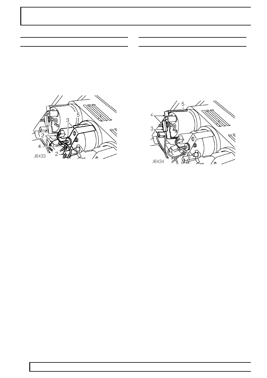
2. Release illumination bulb holder and disconnect
electrical leads from gauge.
3. Unscrew knurled nut and remove clamp
securing gauge.
4. Remove earth lead eylet from gauge stud.
5. Withdraw gauge from instrument panel
Refit
6. Fit gauge into instrument panel, locate earth
lead, and secure with clamp.
7. Fit bulb holder and electrical leads.
8. Fit instrument panel
See Instrument panel .
CLOCK - FASCIA PANEL
Service repair no - 88.15.07
Remove
1. Remove 4 screws securing instrument panel to
fascia cowl.
2. Pull panel away fom fascia sufficient to
disconnect speedometer cable.
3. Disconnect electrical leads and bulb holder from
clock.
4. Unscrew knurled nut and remove clamp
securing clock.
5. Remove clock from instrument panel.
Refit
6. Fit clock into instrument panel and secure with
clamp.
7. Fit bulb holder and electrical leads.
8. Connect speedometer cable.
9. Secure instrument panel to fascia cowl.
Нет комментариевНе стесняйтесь поделиться с нами вашим ценным мнением.
Текст