Discovery 2. Manual — part 602
FRONT SUSPENSION
DESCRIPTION AND OPERATION
60-5
Coil springs
Coil springs are fitted to the front axle of the vehicle. The front springs differ between petrol and Diesel variants. Each
spring is retained at its base by the lower spring seat. The top of each spring is located in the upper spring seat
isolator. The upper spring seat is manufactured from natural rubber , with a bonded metal plate and four bonded studs
which provide for the attachment of the damper turret. The rubber isolator reduces noise transmitted to the chassis
and body from the suspension.
The coil springs must be installed correctly. The bottom coil of the spring locates in a recess in the lower spring seat.
The top coil of the spring is ground flat to locate the upper spring seat isolator.
Coil Spring Specifications – Models up to 03 Model Year
The front springs on petrol variants are manufactured from carbon chrome 13.9 mm (0.55 in) diameter bar. The spring
has 7.6 coils and a free length of 377 mm (14.8 in). The petrol front spring is identified by a pink and orange stripe
painted on a number of coils.
The front springs on Diesel variants are manufactured from carbon chrome 13.9 mm (0.55 in) diameter bar. The spring
has 7.6 coils and a free length of 383 mm (15.0 in). The Diesel front spring is identified by a white and purple stripe
painted on a number of coils.
Coil Spring Specifications – Models from 03 Model Year
The introduction of the 03MY vehicle introduced a range of additional spring fitments. These were introduced to cover
the introduction of the 4.6l V8 engine, the fitment of a front mounted winch and to optimise the vehicle trim heights.
The coil springs are manufactured from silicon manganese 13.8 mm or 13.9 mm (0.54 in or 0.55 in) diameter bar. The
following spring data table shows the colour codes, number of coils and spring free length.
FRONT SUSPENSION
60-6
DESCRIPTION AND OPERATION
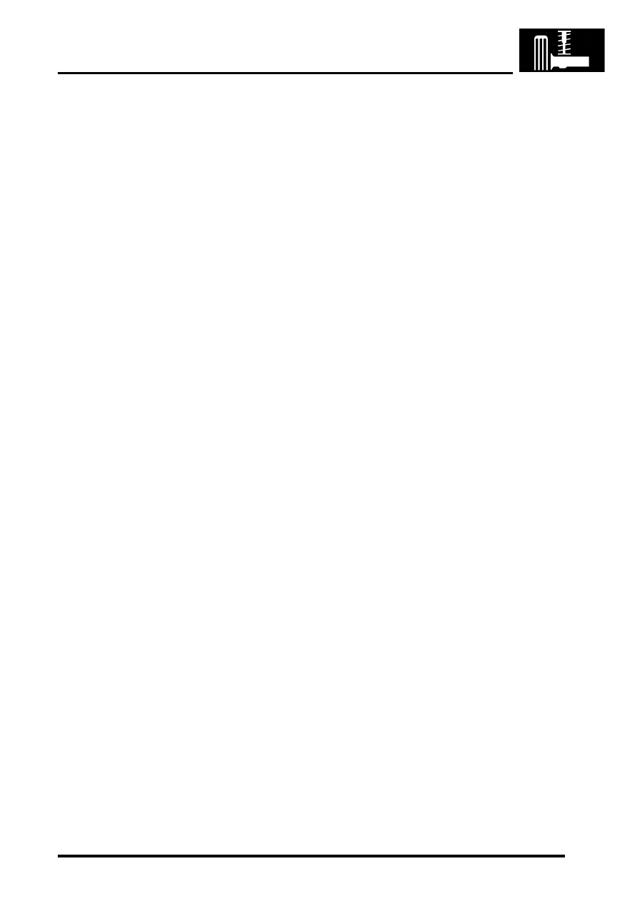
Spring Data
The following table shows spring fitment applicablity.
Spring Fitment Applicability
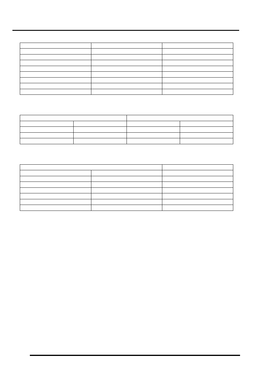
The following table shows standard springs and uprated springs required when a front winch is fitted.
Winch Fitment Spring Applicability
Panhard rod
A Panhard rod is used to ensure that the axle remains centrally located. The Panhard rod has bushes pressed into
housings at each end which provide for the attachment to the axle and chassis. One end of the Panhard rod locates
in a fabricated bracket on the axle and is secured with a bolt and locknut. The opposite end is attached to a fabricated
bracket on the chassis and is also secured with a bolt and a locknut. The Panhard rod is shaped at one end to allow
clearance for the axle casing.
The attachment bolts for the Panhard rod are coated with a clear, dry wax which reduces friction on the bolt and allows
the correct torque to be applied to the clamping of the bushes. The bolts can be re-used, but if bolt replacement is
necessary the correct bolt with the wax coating must be used.
On models from 03 Model Year, the Panhard rod is shortened by 30 mm (1.18 in). This modification was introduced
to enhance the suspension bump steer characteristics in line with other suspension improvements introduced
simultaneously. The change to the Panhard rod also required the relocation of the attachment brackets on the axle
casing and the chassis.
Colour Code
Total No. of Coils
Free Length
Red/Purple
7.4
371 mm (14.6 in)
Yellow/Purple
7.4
378.4 mm (14.9 in)
Blue/Purple
7.4
365 mm (14.4 in)
Grey/Purple
7.4
387 mm (15.2 in)
Purple/Purple
7.4
373.8 mm (14.7 in)
Yellow/Orange
7.4
394.6 mm (15.5 in)
Green/Orange
7.4
382.6 mm (15 in)
Pink/Brown
7.6
405.6 mm (15.9 in)
Left Hand Drive
Right Hand Drive
RH side
LH side
RH side
LH side
Red/Purple
Red/Purple
Yellow/Purple
Blue/Purple
Yellow/Purple
Yellow/Purple
Grey/Purple
Purple/Purple
Grey/Purple
Grey/Purple
Yellow/Orange
Green/Orange
Standard Spring
Winch Fitted Spring
RH Side
LH Side
Both Sides
Red/Purple
Red/Purple
Grey/Purple
Yellow/Purple
Blue/Purple
Yellow/Orange
Yellow/Purple
Yellow/Purple
Yellow/Orange
Grey/Purple
Purple/Purple
Green/Orange
Grey/Purple
Grey/Purple
Green/Orange
Yellow/Orange
Green/Orange
Pink/Brown

FRONT SUSPENSION
DESCRIPTION AND OPERATION
60-7
Torsion/Anti-roll bar
The anti-roll bars fitted differ between ACE and non-ACE vehicles. On non-ACE vehicles a conventional 'passive' anti-
roll bar is used. On ACE vehicles an 'active' torsion bar is used. Both types are attached to the front chassis cross
member with mounting rubbers and clamp plates. The clamp plates locate in brackets on the cross member and are
each secured with a bolt. Each end of the anti-roll bar is attached to an anti-roll bar link. Each link has a spherical
bearing attached at each end. One end is attached to a bracket on the axle and secured with a locknut; a washer is
installed between the spherical bearing and the bracket. The opposite end attaches through a hole in the anti-roll bar
and is secured with a locknut. On 'active' torsion bars, the RH anti-roll bar link is attached to a long arm which in turn
is attached to the torsion bar.
Passive anti-roll bar
The passive anti-roll bar is a conventional anti-roll bar which opposes axle movement, reducing the effects of lateral
forces on the vehicle body.
With the conventional 'passive' anti-roll bar, axle movement is opposed by the anti-roll bar through links attached to
the axle casing and each end of the anti-roll bar. The anti-roll bar is manufactured from 30 mm (1.18 in) diameter
spring steel bar.
Active torsion bar
FRONT SUSPENSION, DESCRIPTION AND OPERATION, Description - ACE.
The 'active' torsion bar is used in conjunction with the ACE system to control body roll and directional stability giving
an improved reduction of the effects of lateral forces on the vehicle body over a conventional anti-roll bar.
The torsion bar opposes axle movement by the application of a hydraulic force to oppose the lateral forces through
links attached to the axle casing and each end of the bar. The torsion bar is made from 35 mm (1.4 in) diameter spring
steel bar. One end is fitted with an arm which is operated by a hydraulic actuator to oppose cornering forces.
FRONT SUSPENSION
60-8
DESCRIPTION AND OPERATION
Нет комментариевНе стесняйтесь поделиться с нами вашим ценным мнением.
Текст