Discovery 2. Manual — part 315

BODY CONTROL UNIT
DESCRIPTION AND OPERATION
86-3-1
BODY CONTROL UNIT
DESCRIPTION AND OPERATION
Description
General
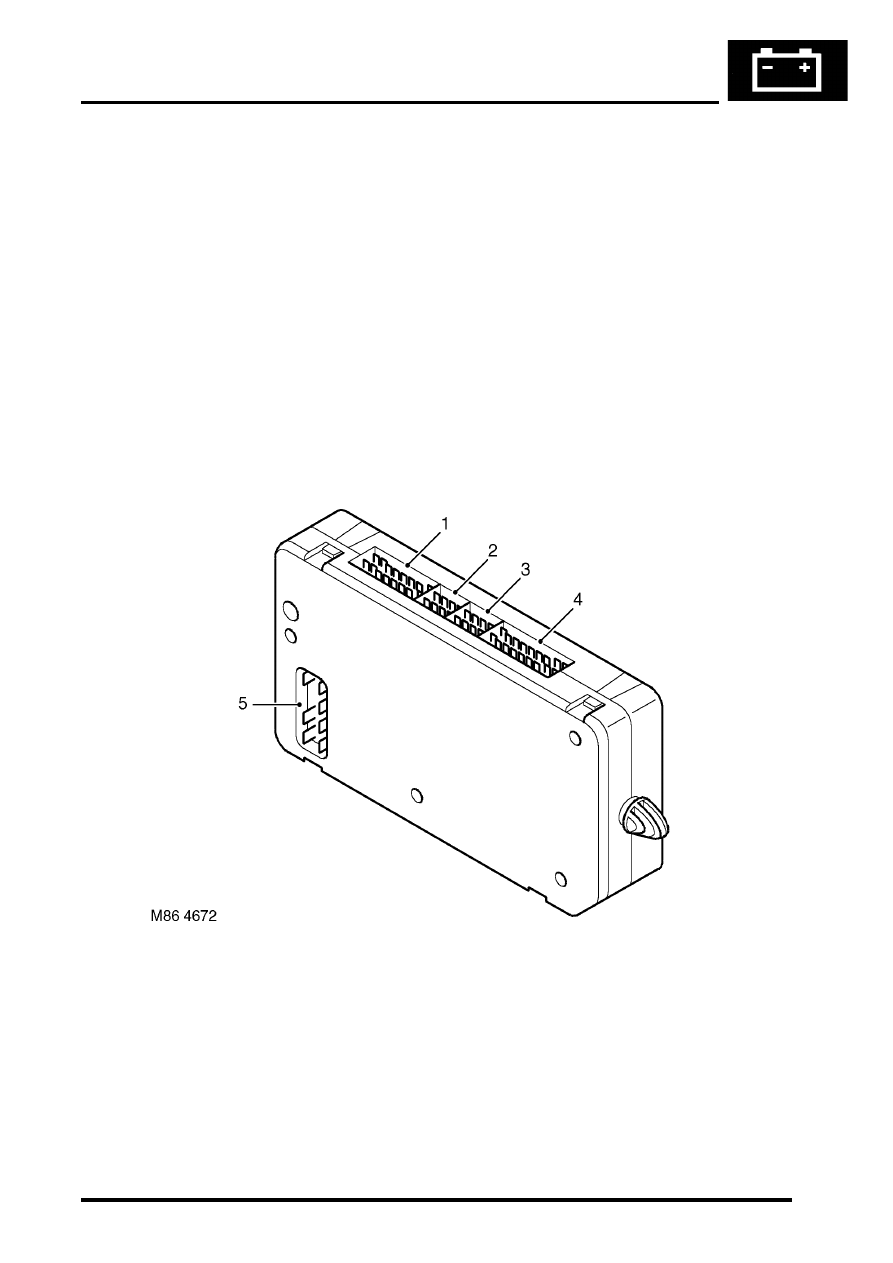
The Body Control Unit (BCU) is located behind the passenger glovebox and is connected to the main harness by four
connectors on its bottom edge and an additional connector located on the side of the BCU casing. Mounting the BCU
behind the fascia makes it reasonably inaccessible for intruders to disable the anti-theft system.
The BCU uses solid-state microprocessor control to perform logical operations and timing functions for a variety of
the vehicle's electrically operated systems, these include:
l
Door locking.
l
Anti-theft alarm and immobilisation system.
l
Exterior lighting including direction indicators and hazard warning lamps.
l
Courtesy lighting.
l
Wipers and washers.
l
Electric windows and sunroof.
l
Heated windows.
The BCU also communicates with several other electronically controlled systems such as the EAT ECU and SLABS
ECU and also has a datalink between the Intelligent Driver Module (IDM) and the instrument pack. The datalink is a
low speed bus capable of transmitting and receiving messages at a data rate of 10,400 bits per second. Additional
inputs and outputs to peripheral devices are included which are necessary for determining vehicle status for particular
logical operations e.g. crank, ignition key inserted, fuel flap enable etc.
The BCU receives its power supply from the engine compartment fuse box, and is protected by a 10 A fuse.
The BCU communicates with the IDM to provide the control signals to perform power switching operations in
conjunction with dedicated relays.
IDM
The IDM is integrated into the passenger compartment fuse box, which is mounted behind the fascia below the
steering column. There are no harnesses between the fuse box and the IDM. The IDM performs the power switching
operations for several of the vehicle's electrical systems.
The IDM communicates with the BCU and the instrument pack via a serial interface. If the BCU or the IDM is replaced,
the communications link between the two units has to be re-established. This can be done either by switching on the
ignition and leaving it on for five minutes, or by using TestBook. The vehicle immobilisation will remain active until the
communications link between the BCU and IDM has been re-established.
Transit mode
To prevent excessive battery drain during transit to overseas markets, the vehicle is placed in a transit mode. The
following functions are disabled when the vehicle is in transit mode:
l
Volumetric sensors.
l
Passive immobilisation.
l
Immobilisation of the vehicle by use of door lock.
l
Ignition key interlock.
l
Electric seat enable time-out with driver's door open.
BODY CONTROL UNIT
86-3-2
DESCRIPTION AND OPERATION
Power supply
Battery supply to the BCU and the IDM is provided through a 10 A fuse located in the engine compartment fuse box.
The BCU unit receives an ignition switched power supply (ignition switch position II) input via a 10 A fuse in the
passenger compartment fuse box.
The BCU receives a signal when the ignition switch is turned to the crank position, it then supplies an earth path to
the starter relay coil, to enable the crank operation by supplying power through the starter relay contacts to the starter
motor.
Battery voltage is monitored and BCU operation will function normally between 8 and 18 volts. Between 5.7 and 8
volts the BCU is in the 'under volts' state. The status of the battery is used to determine which outputs may be driven.
If a voltage supply above 18 volts is experienced, outputs will not normally be driven except for those functions which
are required during cranking (robust immobilisation, antenna coil, crank enable relay and feed to gear position switch
contacts W, X, Y, Z). In the over voltage state the vehicle can be driven, but all other functions are disabled and
outputs are switched off (power windows, heated screen, direction indicators etc.).
All functions are disabled on power up until communications between the BCU and IDM have been established. If
communications cannot be established, operation will commence with degraded functionality.
Battery supply to the IDM is provided through the inertia switch and a 10 A fuse in the engine compartment fuse box.
If the inertia switch contacts are closed battery voltage is available at the IDM; if the inertia switch contacts are open
there is no battery supply to the IDM. The supply condition of the IDM is signalled to the BCU via the serial bus. If the
inertia switch is operated (contacts open) the change in state is detected by the BCU which unlocks the doors if the
ignition switch is in position II and the alarm is not set.
The BCU is earthed through a hard-wire connection.
Inputs and outputs
The BCU and IDM process inputs and provide the necessary outputs for control and operation of the vehicle's 'body'
systems.
BCU inputs
The BCU processes signals received from the following components:
l
Door latch switches.
l
Driver's door key lock/ unlock switches.
l
Bonnet activated security system.
l
Volumetric sensors.
l
Central Door Locking (CDL) switches.
l
Remote transmitter (via receiver unit).
l
Inertia fuel cut-off switch.
l
Ignition switch.
l
Fuel flap release switch.
The input voltages (V
in
) for BCU digital signals are defined as follows:
l
Logic 1 when V
in
≥
6V.
l
Logic 0 when V
in
≤
2V.
BCU input voltages between 2 and 6 volts are indeterminate and cannot be guaranteed.
Analogue input voltages are measured as a ratio with respect to battery voltage.
BODY CONTROL UNIT
DESCRIPTION AND OPERATION
86-3-3
BCU outputs
The BCU processes the input signals it receives and uses the information to determine the control outputs that need
to be established for any given set of conditions. The BCU provides controlled outputs for the following systems:
l
Interior courtesy lamps.
l
Fuel flap release actuator.
l
Anti-theft status LED.
l
Engine Control Module.
l
Door lock actuators.
l
Direction indicators and hazard warning lamps.
l
Headlamps.
l
Alarm sounder.
l
Vehicle horns.
l
Battery backed sounder.
l
Starter relay.
l
Passive re-mobilisation exciter coil.
Simultaneous switching of outputs in different units is limited by the bus transfer time, but the skew is no longer than
100 ms for either the BCU or the IDM. When the processor is reset, all outputs are switched off until the inputs have
been read for the first time to check current condition.
BCU to harness connectors
1 Connector C0661
2 Connector C0662
3 Connector C0663
4 Connector C0660
5 Connector C0664
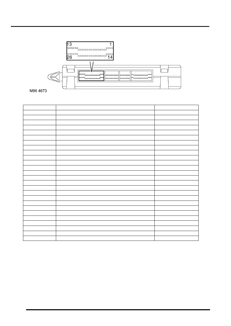
The pinout details for the BCU connectors are defined below:
BODY CONTROL UNIT
86-3-4
DESCRIPTION AND OPERATION
C0660 connector pin details
Pin No.
Description
Input/Output
1
Ignition power supply
Input
2
Right front window - down
Input
3
Auxiliary power supply
Input
4
Passenger or rear door open
Input
5
Driver's door key lock
Input
6
RH indicator selected
Input
7
Front fog lamps selected
Input
8
Gear position feedback 'R'
Output
9
Gear position feedback 'P'
Output
10
SLS too high (audible warning)
Input
11
Earth
-
12
Vehicle raise/lower request
Output
13
Battery power supply
Input
14
Heated front screen selected
Input
15
Bonnet open
Input
16
CDL doors lock
Input
17
Driver's door open
Input
18
Left front window up
Input
19
Right front window up
Input
20
Rear washer pump
Input
21
Front intermittent wiper switch
Input
22
Gear position feedback '1'
Output
23
Gear position feedback '2'
Output
24
Gear position feedback '3'
Output
25
Gear position feedback 'D'
Output
26
Gear position feedback 'N'
Output
Нет комментариевНе стесняйтесь поделиться с нами вашим ценным мнением.
Текст