Discovery 2. Manual — part 316
BODY CONTROL UNIT
DESCRIPTION AND OPERATION
86-3-5
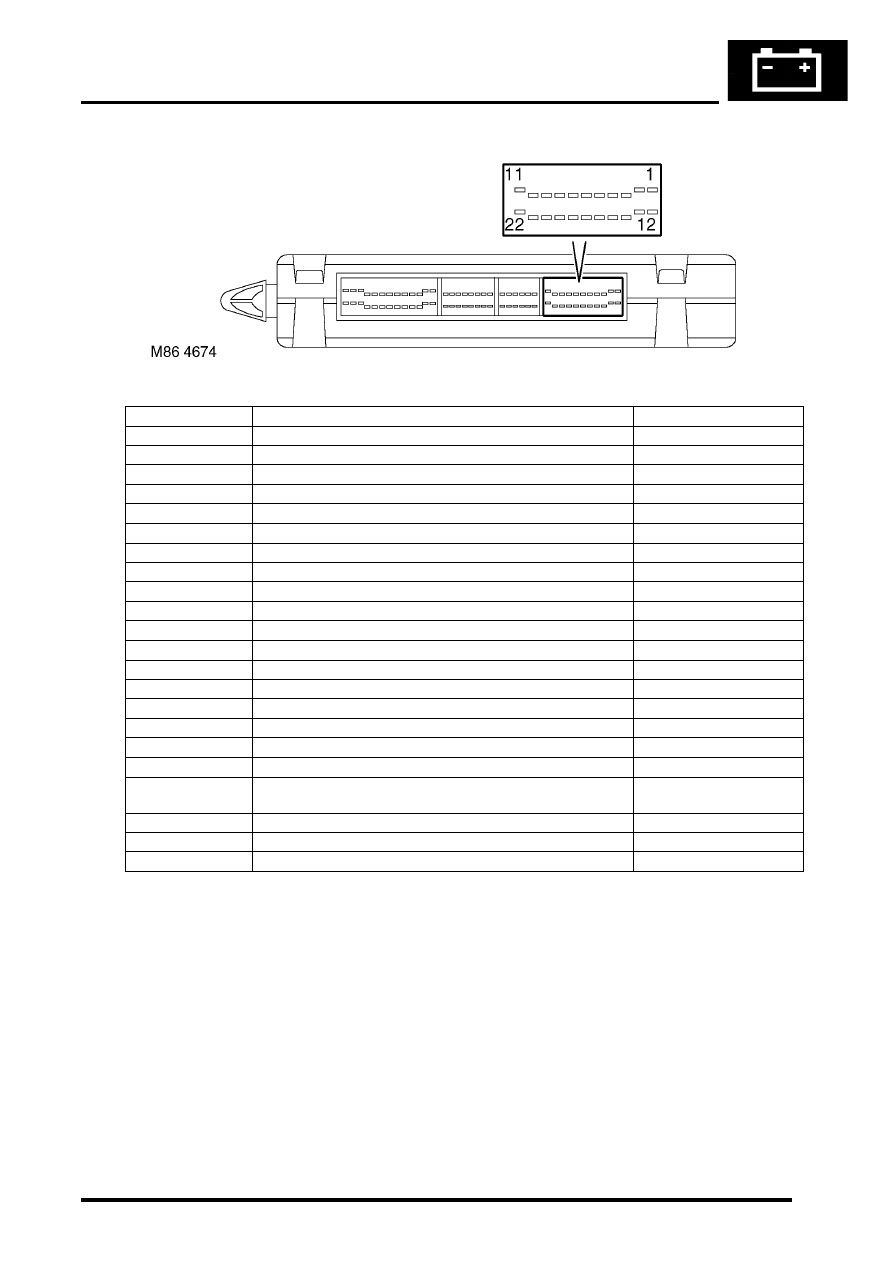
C0661 connector pin details
Pin No.
Description
Input/Output
1
Serial bus to instrument pack and IDM
Input/Output
2
Not used
-
3
Battery backed up sounder code (AL)
Output
4
Diagnostic bi-directional 'K'-line
Input/Output
5
RF regulated power supply
Output
6
RF receiver input
Input
7
Brake switch activated
Input
8
Reverse gear selected
Input
9
Sunroof enable line
Output
10
Robust immobilisation
Output
11
Front washer pump
Input
12
Heated front screen relay
Output
13
Heated front screen active
Output
14
Battery backed up sounder code (ST)
Output
15
Heated rear screen active
Output
16
'N' or 'R' or 'P' or brake selected
Output
17
Not used
-
18
Passive remobilisation exciter coil
Output
19
RF battery supply from fuse 20 in passenger compartment
fusebox
Input
20
Security status LED
Output
21
Front intermittent wiper
Input
22
Driver's door key unlock
Input
BODY CONTROL UNIT
86-3-6
DESCRIPTION AND OPERATION
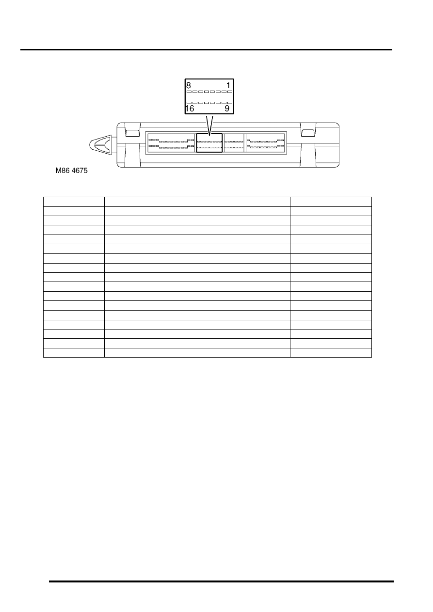
C0662 connector pin details
Pin No.
Description
Input/Output
1
Front left window - down
Input
2
Ignition key inserted
Input
3
Rear wiper
Input
4
Vehicle horns
Input
5
Crank enable
Output
6
Gear position switch (Y contacts)
Input
7
CDL doors unlock
Input
8
Rear fog lamps selected
Input
9
Gear position switch (W contacts)
Input
10
Drive selected (HDC)
Output
11
Ignition key interlock solenoid
Output
12
Headlamp powerwash
Output
13
Gear position switch (X contacts)
Input
14
Not used
-
15
Transfer box - neutral selected
Input
16
Seat buckle fastened
Input
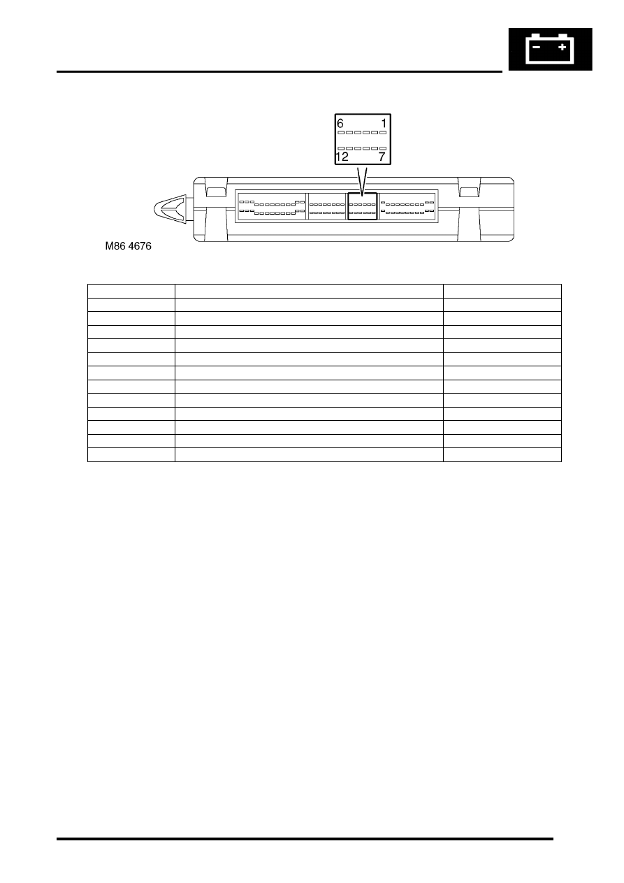
BODY CONTROL UNIT
DESCRIPTION AND OPERATION
86-3-7
C0663 connector pin details
Pin No.
Description
Input/Output
1
Crank selected
Input
2
LH direction indicator selected
Input
3
Driver/Passenger seat enable
Output
4
Front fog lamps
Output
5
Heated rear screen selected
Input
6
Ultrasonic input
Input
7
Gear position switch (Z contacts)
Input
8
Ultrasonic power supply
Output
9
Courtesy lamps
Output
10
Feed to gear position switch (W, X, Y, Z contacts)
Output
11
Park/Neutral selected
Input
12
Hazard warning lamps
Input
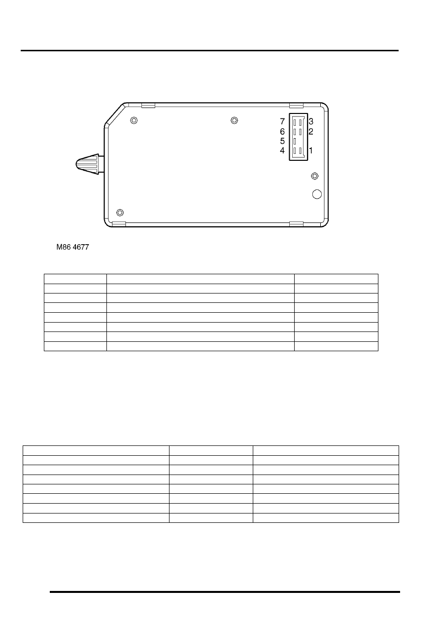
BODY CONTROL UNIT
86-3-8
DESCRIPTION AND OPERATION
C0664 connector pin details
IDM inputs
The IDM inputs are communicated to the BCU using the serial datalink so that the BCU can perform the necessary
logic operations:
The V
in
for IDM digital signals are defined as follows:
l
Logic 1 when V
in
≥
8V.
l
Logic 0 when V
in
≤
2V.
IDM input voltages between 2 and 8 volts are indeterminate and cannot be guaranteed.
Pin No.
Description
Input/Output
1
Front left window down
Output
2
Front right window down
Output
3
Fuel flap release
Output
4
Front left window up
Output
5
Earth
-
6
Front right window up
Output
7
Battery power supply
Input
Description
Signal type
System
Inertia switch
Digital
Locking/ Unlocking/ Alarm
Side lamps
Digital
Exterior lighting
Headlamp dipped beam
Digital
Exterior lighting
Headlamp main beam daylight running lamps
Analogue
Exterior lighting
RH direction indicators current sense
Analogue
Direction indicators/ Hazards/ Alarm
LH direction indicators current sense
Analogue
Direction indicators/ Hazards/ Alarm
Front wiper park sense
Digital
Wipers and washers
Нет комментариевНе стесняйтесь поделиться с нами вашим ценным мнением.
Текст