Discovery 2. Manual — part 471

ENGINE MANAGEMENT SYSTEM - TD5
DESCRIPTION AND OPERATION 18-1-27
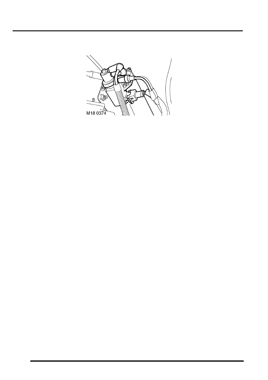
Clutch switch
The clutch switch is located at the rear of the engine compartment on the RH side. The switch is operated by hydraulic
pressure when the clutch pedal is pressed. The ECM uses the signal from the clutch switch for the following functions:
l
To cancel cruise control if operating.
l
To provide surge damping during gear change.
Surge damping stops engine speed rising dramatically (engine flaring) during gear change. Surge damping assists
driveability as follows:
l
Smoother gear change.
l
Greater exhaust gas emission control.
l
Improved fuel consumption.
Input/Output
The clutch switch receives battery voltage from the BCU. With the clutch pedal in the rest position the switch is closed,
allowing battery voltage to pin 35 of the ECM connector C0658. When the clutch pedal is pressed the switch contacts
open, interrupting the power supply to the ECM. The ECM receives 0 Volts.
The clutch switch can fail in the following ways:
l
Switch open circuit.
l
Short circuit to vehicle supply.
l
Short circuit to earth.
In the event of a clutch switch failure the ECM will react as follows:
l
Surge damping will be inactive.
l
Cruise control will be inactive.
High/Low ratio switch
Refer to transfer box for description of the high/low ratio switch.
TRANSFER BOX - LT230SE, DESCRIPTION AND OPERATION, Description.
ENGINE MANAGEMENT SYSTEM - TD5
18-1-28 DESCRIPTION AND OPERATION
Exhaust Gas Regulator (EGR) modulator
The EGR modulator is located in the engine compartment on the offside inner wing. It regulates the vacuum source
to the EGR valve allowing it to open or close. The ECM utilises the EGR modulator to control the amount of exhaust
gas being recirculated in order to reduce exhaust emissions and combustion noise. Optimum EGR is usually obtained
when the vehicle is operating at light throttle openings, and the vehicle is cruising at approximately 2000 to 3000 rev/
min.
Input/Output
The EGR modulator receives battery voltage from fuse 2 in the engine compartment fuse box. The earth path is via
pin 3 of ECM connector C0158. The length of time that the ECM supplies an earth is how long the exhaust gases are
allowed to recirculate. The ECM decides how long to supply the earth for by looking at engine temperature and engine
load.
The EGR can fail in the following ways:
l
Solenoid open circuit.
l
Short circuit to vehicle supply.
l
Short circuit to earth.
In the event of an EGR modulator failure the EGR system will become inoperative.
The MIL will not illuminate in the event of an EGR modulator failure.
ENGINE MANAGEMENT SYSTEM - TD5
DESCRIPTION AND OPERATION 18-1-29
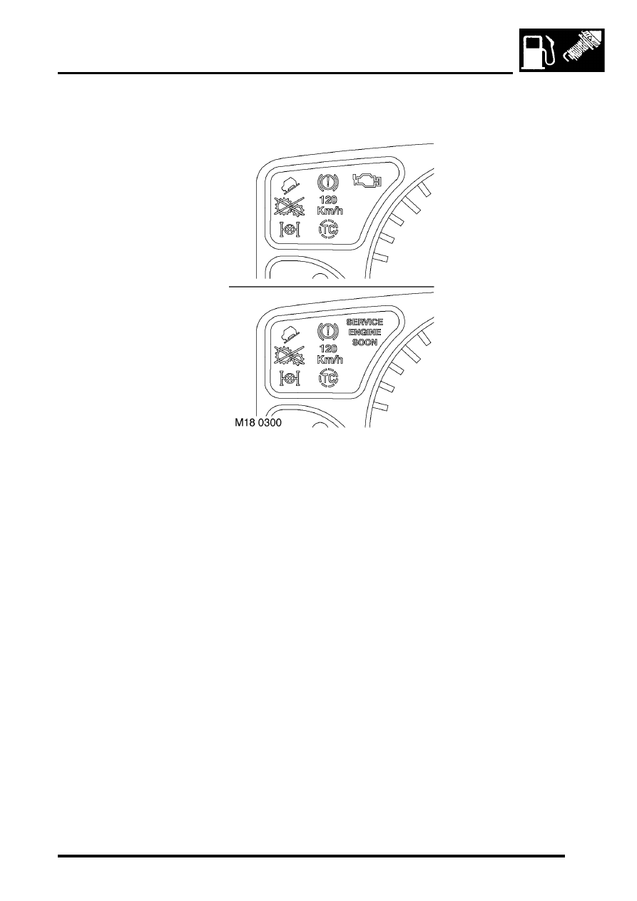
Malfunction Indicator Lamp (MIL)
The MIL is located in the instrument cluster. It illuminates to alert the driver to system malfunctions. During ignition a
self-test function of the lamp is carried out. The lamp will illuminate for 3 seconds then extinguish if no faults exist. If
a fault is present the lamp will be extinguished for 1 second before illuminating.
Input/Output
The MIL is supplied with battery voltage from the instrument cluster. When the ECM detects a fault, it provides an
earth path to illuminate the MIL. The earth path is via pin 6 of ECM connector C0658.
ENGINE MANAGEMENT SYSTEM - TD5
18-1-30 DESCRIPTION AND OPERATION
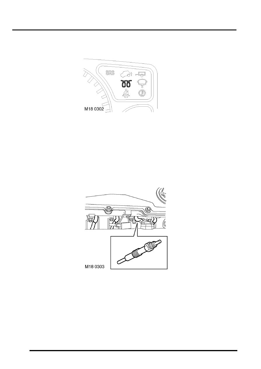
Glow plug warning lamp
The glow plug warning lamp is located in the instrument cluster. It illuminates to alert the driver that the glow plugs
are being heated prior to the engine being started. The length of time that the lamp illuminates and the glow plugs
are operating prior to cranking is the pre-heat period, which is subject to battery voltage and ECT sensor signal
controlled by the ECM.
Input/Output
The instrument cluster supplies battery voltage to the glow plug warning lamp. The ECM provides an earth path to
illuminate the lamp. The earth path is via pin 30 of ECM connector C0658.
Glow plugs
The 4 glow plugs are located in the engine block on the inlet side, in cylinder 1 to 4. Cylinder 5 has no glow plug. The
glow plugs are a vital part of the engine starting strategy.
Нет комментариевНе стесняйтесь поделиться с нами вашим ценным мнением.
Текст