Discovery 2. Manual — part 469
ENGINE MANAGEMENT SYSTEM - TD5
DESCRIPTION AND OPERATION 18-1-19
Throttle Position (TP) sensor – From VIN 297137
Discovery Series II vehicles from VIN 297137 use three track thick film potentiometers. No idle speed sender switch
is used on this type of sensor because the ECM can compare the two or three sets of signals to implement idle speed
control and over-run fuel shut-off. The two potentiometers are known as track 1 and 2 potentiometers. The track 3
potentiometer on later models is used to improve the resolution of the pedal. The ECM provides a 5V supply and
receives a signal from each of the potentiometer tracks.
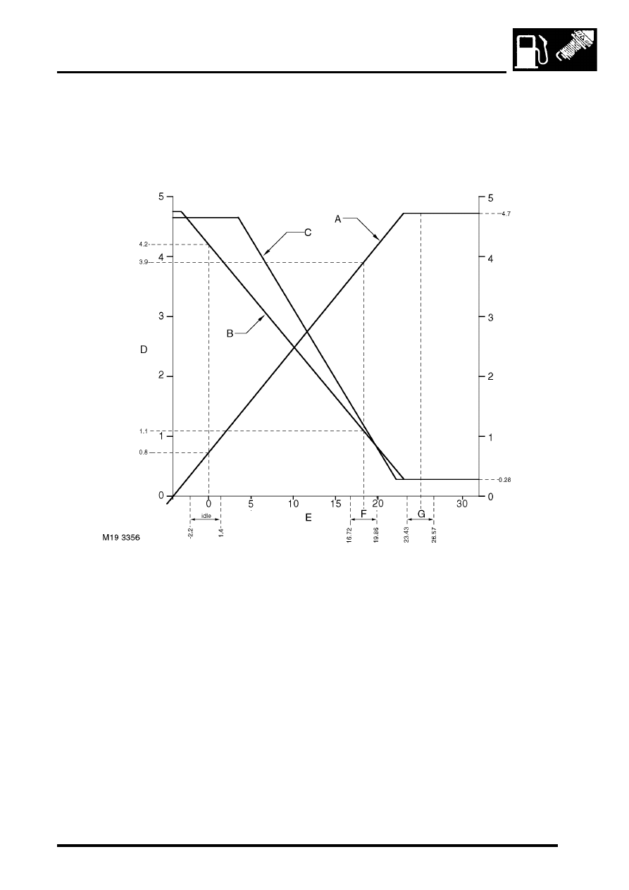
a = Track 1
b = Track 2
c = Track 3
d = Voltage
e = Pedal angle (degrees)
f = Wide open throttle stop tolerance band
g = Not applicable for Discovery Series II.
With reference to the above graph, at idle (throttle released), track 2 returns a signal of 4.2V to the ECM and track 1
returns a signal of 0.8V. The ECM calculates the sum of these two figures which totals 5.0V.
At wide open throttle, track 2 returns a signal of 1.1V and track 1 returns a signal of 3.9V to the ECM. The ECM
calculates the sum of these two figures which totals 5.0V. The ECM uses this strategy to error check the TP sensor
signal and ensure that the requested throttle position is applied. The third potentiometer track measures the tolerance
of tracks 1 and 2 and provides an improved functionality check of the pedal angle.
NOTE: Three track TP sensors cannot be fitted as replacements on vehicles previously fitted with two track TP
sensors. Replacement ECM's are configured for two track TP sensors and can be fitted to all Td5 models. When
replacement ECM's are fitted to vehicles using three track TP sensors, TestBook or T4 must be used to configure the
ECM for three track TP sensor use.
If the TP sensor fails, the ECM will illuminate the MIL and the engine will operate at normal idle speed only.
ENGINE MANAGEMENT SYSTEM - TD5
18-1-20 DESCRIPTION AND OPERATION
Electronic Unit Injector (EUI)
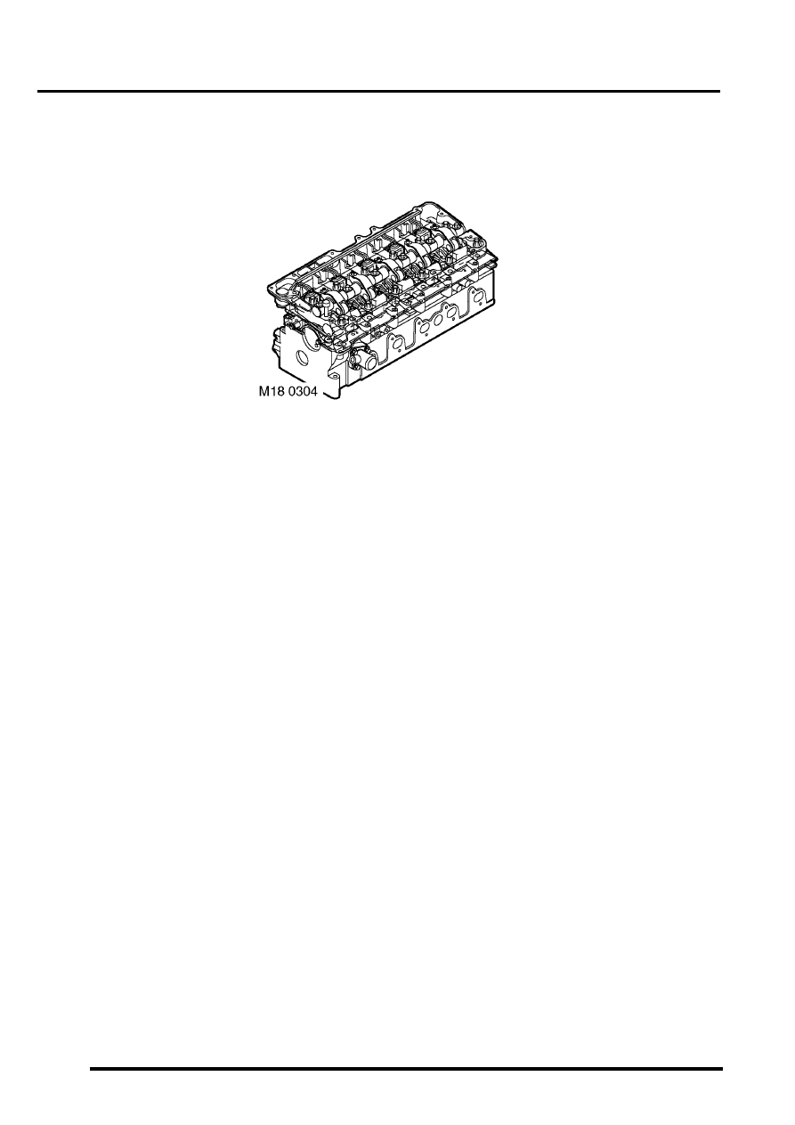
The EUI's are located in the top of the engine inside the camshaft cover. There is one EUI per cylinder. They inject
finely atomised fuel directly into the combustion chamber. Each EUI has its own electrical connection, which is linked
to a common harness also located under the camshaft cover. Each of the EUI has its own 5 letter grading code. This
code is used so that greater EUI precision is achieved.
The ECM provides the earth path for the EUI. Using an injection-timing map within its memory and information from
the crankshaft speed and position sensor the ECM is able to determine precise crankshaft angle. When the ECM
determines the crankshaft speed and position it closes the spill valve within the EUI. Fuel pressure rises inside the
EUI to a predetermined limit of, 1500 bar (22,000 lbf.in
2
) on pre EU3 models, and 1750 bar (25,500 lbf.in
2
) on EU3
models, at this limit the pintle lifts off its seat allowing the fuel to inject into the combustion chamber. The ECM de-
energises the spill valve to control the quantity of fuel delivered. This causes a rapid pressure drop within the EUI
which allows the EUI return spring to re-seat the pintle ending fuel delivery.
The electrical circuit that drives the EUI works in two stages depending on battery voltage. If battery voltage is
between 9 and 16 volts the EUI's will provide normal engine performance. If however battery voltage falls to between
6 and 9 volts, on pre EU3 models, EUI operation is restricted to a limit of 2100 rev/min, on EU3 models EUI operation
is restricted to idle.
If the vehicle is fitted with a new ECM, the EUI grades for that specific vehicle must be downloaded to the new ECM
using TestBook. In the event of the engine failing to rev above 3000 rev/min it is probable that the EUI grading has
not been completed.
Input/Output
Input to the EUI takes the form of both mechanical and electrical signals. The mechanical input to the EUI is diesel
fuel via the fuel pump operating at approximately 4 to 5 bar (58 to 72 lbf.in
2
). Each of the EUI's is operated
mechanically by an overhead camshaft to enable injection pressures of up to 1500 bar (22,000 lbf.in
2
) on pre EU3
models, and 1750 bar (25,500 lbf.in
2
) on EU3 models, to be achieved. The ECM controls the EUI's to ensure that fuel
delivery is precise and as intended.

ENGINE MANAGEMENT SYSTEM - TD5
DESCRIPTION AND OPERATION 18-1-21
The EUI's earth paths are as follows:
l
EUI 1 via pin 25 of the ECM connector C0158.
l
EUI 2 via pin 26 of the ECM connector C0158.
l
EUI 3 via pin 27 of the ECM connector C0158.
l
EUI 4 via pin 24 of the ECM connector C0158.
l
EUI 5 via pin 1 of the ECM connector C0158.
The EUI can fail as follows:
l
Open circuit.
l
Short circuit to voltage supply.
l
Short circuit to vehicle earth.
l
Wiring loom fault.
l
Connector water ingress.
l
Connector failure due to excess heat.
In the event of a fuel injector failure any of the following symptoms may be observed:
l
Engine misfire.
l
Idle faults.
l
Reduced engine performance.
l
Reduced fuel economy.
l
Difficult cold start.
l
Difficult hot start.
l
Excess smoke.
ENGINE MANAGEMENT SYSTEM - TD5
18-1-22 DESCRIPTION AND OPERATION
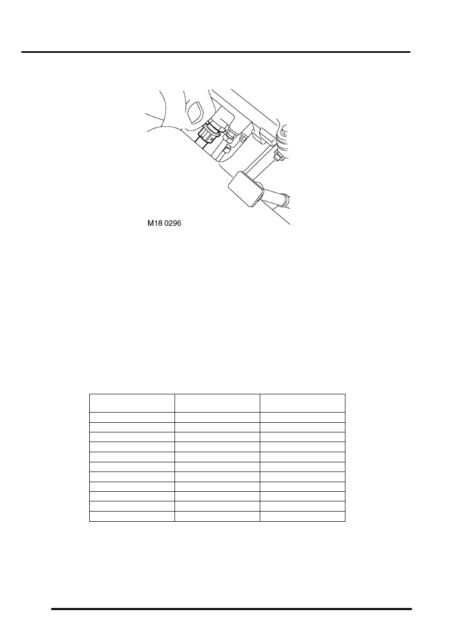
Fuel Temperature (FT) sensor
The FT sensor is located at the rear of the engine in the fuel rail with the tip of the sensor inserted at least 10 mm into
the fuel flow. This allows the sensor to respond correctly to changes in fuel density in relation to fuel temperature.
The FT sensor works as a NTC sensor. As fuel temperature rises the resistance in the sensor decreases. As
temperature decreases the resistance in the sensor increases. The ECM is able to compare the voltage signal to
stored values and compensates fuel delivery as necessary for hot engine start.
The operating range of the sensor is -40 to 130
°
C (-40 to 266
°
F).
Input/Output
The inputs and outputs for the FT sensor are 5 volt supply and signal out. In the event of component failure the ECM
reverts to a fixed value of 60
°
C stored in its memory.
The output signal is measured via pin 19 of the ECM connector C0158. The earth path is via pin 5 of ECM connector
C0158.
FT sensor temperature to resistance table.
Temperature,
°
C
Temperature,
°
F
Resistance, ohms
(nominal)
-10
14
9397
0
32
5896
10
50
3792
20
68
2500
30
86
1707
40
104
1175
50
122
834.0
60
140
595.5
80
176
322.5
100
212
186.6
125
257
100.2
Нет комментариевНе стесняйтесь поделиться с нами вашим ценным мнением.
Текст