Defender (1993+). Manual — part 13
CLEAN PLENUM CHAMBER VENTILATION
7 . Any remaining consolidated matter can
be
PASSAGEWAY
dislodged using a piece of soft bent
wire
or
a
pipe cleaner. Finally the passageway must
The cleaning of the plenum chamber ventilation
again be blown out to remove any remaining
passageway can be carried out without removing the
debris.
plenum chamber from the ram housing.
8.
Remove the small
'T'
piece between the
crankcase ventilation hoses and check that
it
CAUTION:
Care must be taken to prevent debris
is free from blockages, clean as necessary
from the passageway passing beyond the throttle
9.
Refit the ‘T’ piece and hoses, tighten the hose
valve disc.
clamps securely.
WARNING:
Safety glasses must
be
worn when
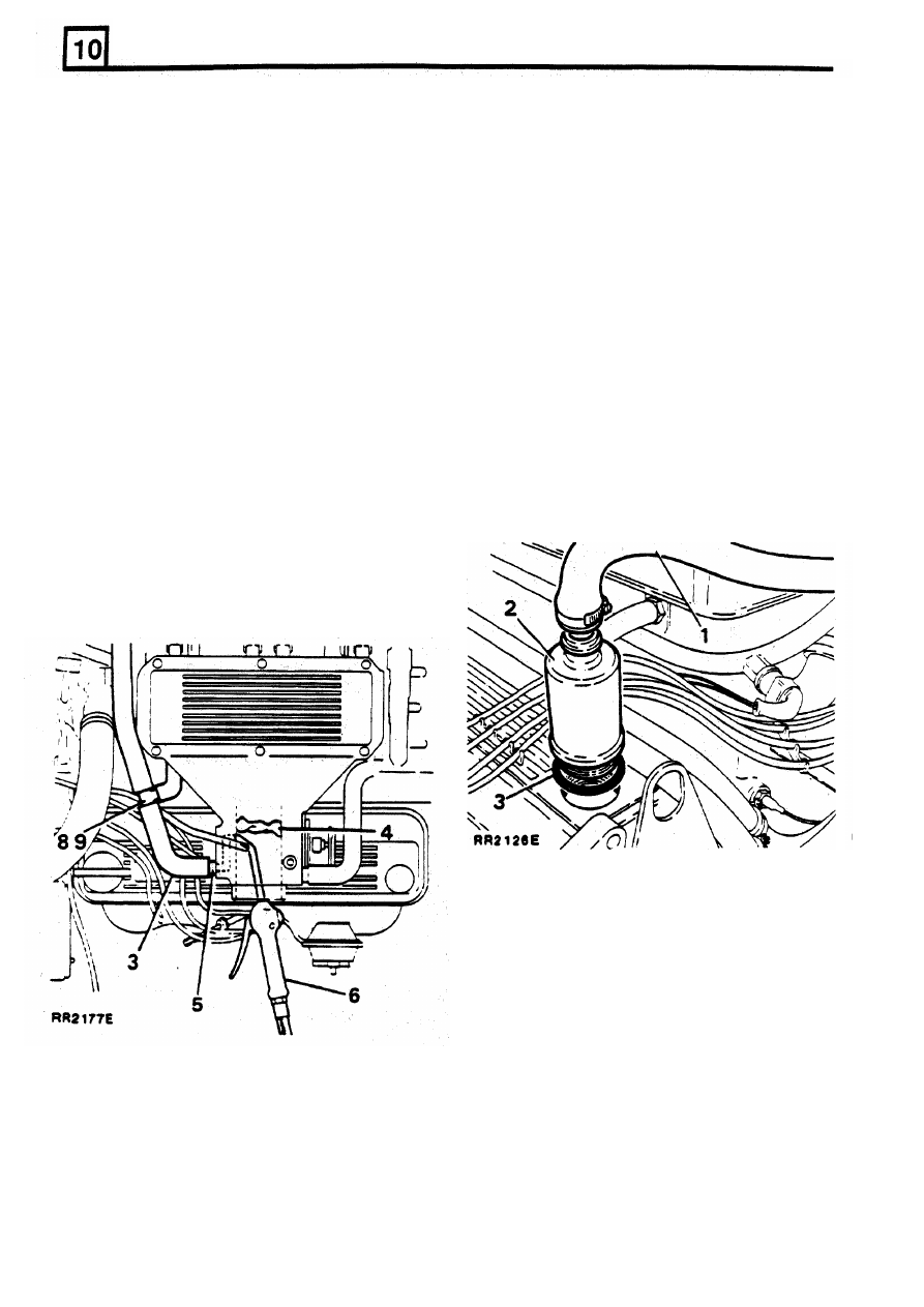
CLEAN POSITIVE CRANKCASE VENTILATION
performing this operation. Ensure that debris
is
not blown into the atmosphere which could be
harmful to other personnel within the vicinity.
1.
Release the hose clamp and pull the hose off
the canister.
1.
Disconnect the battery negative terminal.
2.
Unscrew the canister and remove if from the
2.
Release the hose clamp and remove the hose
rocker cover.
from the plenum chamber inlet neck.
3.
Remove the large
'O'
ring from the threaded
3.
Remove the crankcase ventilation hose from
end
of
the canister.
the side of the plenum chamber.
4.
Visually
inspect
the condition
of
the wire
4.
Insert a piece of lint free cloth down the
screen within the canister, if
in
poor condition
throttle valve bore to prevent debris passing
fit a new assembly, if in an acceptable
beyond the throttle valve.
5.
Place a cloth over the tube protruding from
the side
of
the plenum from which the
ventilation hose was removed to prevent
debris from the passageway being blown into
the atmosphere.
BREATHER FILTER
condition clean the screen as follows:
5.
Immerse the canister in
a
small amount
of
solvent and allow
time
tor the solvent
10
dissolve and loosen
any
engine fume debris
within the canister.
6.
Remove canister from solvent bath and allow
to dry out in still air.
WARNING:
Do not use a compressed air line to
remove any remaining solvent or particles of
debris within the canister as this could cause fire
or personal injury.
Refitting the breather/filter
6.
Use a compressed air
line
with a slim bent
nozzle to enable the passageway to be
cleaned out from
within
the throttle valve bore.
7
8.
Screw the canister into the rocker cover hand
9.
Refit hose and tighten hose clamp securely
Fit a new rubber
'0'
ring.
tight only.
I
18
RE-ISSUED: FEB 1993
MAINTENANCE
RR2171E
MAINTENANCE
RR1876E
GENERAL MAINTENANCE AND ADJUSTMENTS
CHECK/ADJUST OPERATION
OF
ALL WASHERS
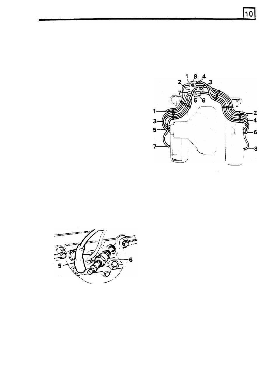
9.
Ensure that replacement H.T. leads are
AND TOP-UP RESERVOIR
refitted in their spacing cleats in accordance
with the correct layout illustrated.
Failure
to
observe this instruction may result
in cross-firing between two closely fitted leads
which are consecutive in the firing order.
Fitting H.T.
leads
1.
Check the operation of windscreen, tailgate
and headlamp washers.
2.
Adjust jets
if
necessary by inserting a needle
or
very fine sharp implement into the jet orifice
and maneuvering
to
alter the jet direction.
3.
Unclip the reservoir cap.
4.
Top up reservoir to within 25mm
(1
in) below
the bottom of the filler neck.
Use a screen washer soIvent/anti-freeze in the
reservoir, this will assist in removing mud,
flies and road film and protect against
freezing.
IGNITION
Spark plugs
1.
Take great care when fitting spark plugs not
to cross-thread the plug, otherwise costly
damage to the cylinder head will result.
2. Check or replace the spark plugs as
applicable.
3.
It is important that only the correct type
of
spark plugs are used
for
replacements.
4.
Incorrect grades
of
plugs may lead
to
piston
overheating and engine failure.
To remove spark plugs proceed as
follows:
5.
Disconnect the battery negative lead and
remove the leads
from
the
spark plugs.
6. Remove the' plugs
and
washers.
7.
Set
the electrode gap to the recommended
clearance.
8.
When pushing the leads onto the plugs,
ensure that the shrouds are firmly seated on
the plugs.
RE-ISSUED:
FEB
1993
19
MAINTENANCE
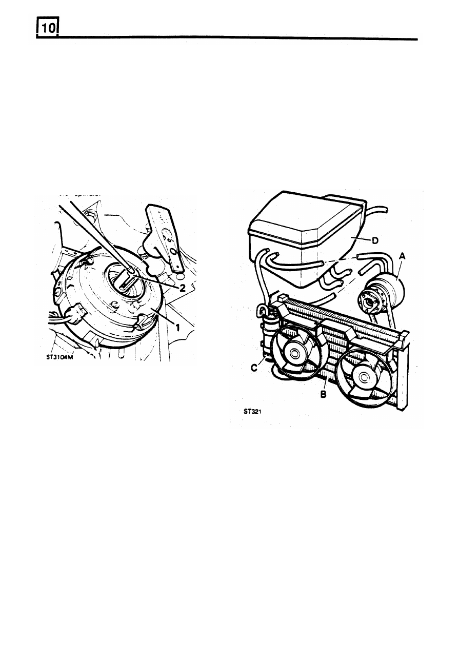
CLEAN AND LUBRICATE V8 ENGINE
AIR CONDITIONING SYSTEM DEFENDER 110
ELECTRONIC DISTRIBUTOR every 40,000 km
(24,000 miles)
The air conditioning system operates in conjunction
with
the vehicle heater
to
provide dried cooled
WARNING:
The electronic
ignition
System
recirculated or fresh air to the vehicle interior
involves very high voltages.
Inexperienced
The system consists
of
the following units which
personnel and wearers of medical pacemaker
should be examined at the same mileage intervals
devices should not be allowed near any part
of
as the heater system:
the high tension circuit.
1.
Remove the distributor cap and rotor arm and
wipe inside with a nap-free cloth.
Do
not
disturb the clear plastic insulating cover which
protects
the magnetic pick-up module.
2.
Apply three drops
of
clean engine oil to the
rotor spindle
A.
Engine mounted compressor.
B. Condenser in front of the radiator.
C.
A
receiver/drier in front
of
and to the right of
the condenser.
D.
Evaporator/heater unit in engine compartment
3.
Fit the rotor arm and distributor cap and
ensure that the
cap
is property located and
secured with the
two
clips.
1.
Compressor: Check the pipe connections tor
leakage and the hoses tor swelling Check
that the drive belt is correctly tensioned
2. Condenser: Using an air line. or a water
hose, dean the exterior of the condenser
matrix. Check the pipe Connections for signs
of leakage.
20
REVISED
OCT
1993
ST3150M
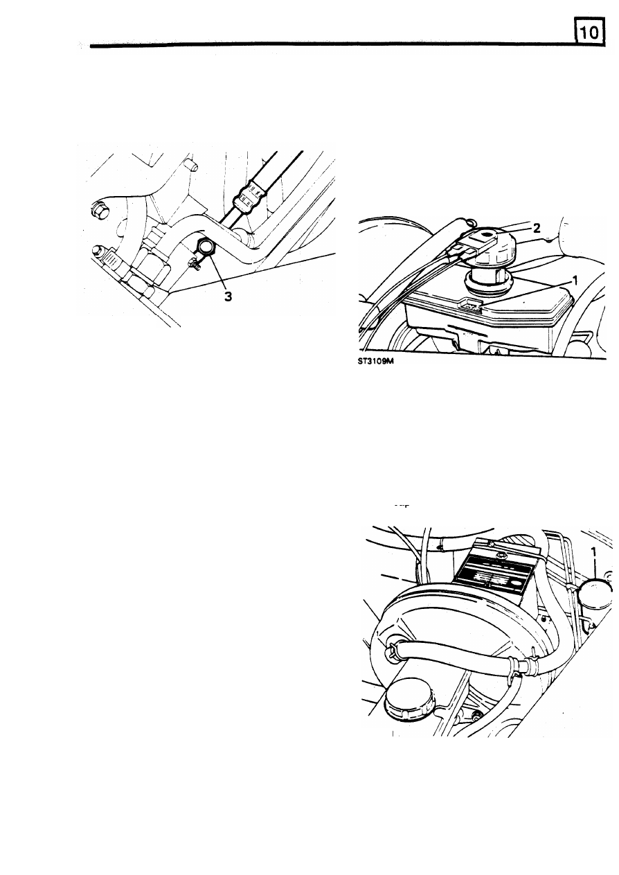
MAINTENANCE
3.
Receiver/drier: Check the pipe connections
CHECK BRAKE FLUID RESERVOIR
for signs of leakage. Examine the sight glass
while the system is operating and
if
bubbles
are present
it
indicates that the system is
contaminated
with
air or water and
will
require
purging.
reservoir.
1.
Check the fluid level in the fluid reservoir
by
observing the level in relation
to
the 'MIN’
or
'MAX'
marks on the side of the translucent
2. If
the level is below the 'MAX' mark clean the
outside of the filler cap and top-up with new.
clean fluid from a sealed container.
Use
only
fluid recommended in
'SECTION 09'.
Refit the
cap.
4.
Evaporator: Examine the pipe connections for
leaks.
WARNING:
The air conditioning system
is
filled
at high pressure with a potentially toxic material.
If any repair or servicing work
is
necessary
following the above inspections, it
must
only
be
carried
out
by a qualified air conditioning
on the side
of
the
reservoir.
engineer who must wear protective goggles and
follow the WARNINGS and CAUTIONS given
in
SECTION 82.
CHECK
C
L
U
TCH
F
LU
I
D RESERVOIR
1.
Clean and remove the reservoir cap and
observe the fluid level in relation to the marks
2.
Top-up if necessary with new, clean fluid
from
a sealed container and
of
a recommended
specification -
see
'SECTION 09'.
Refit
the
cap.
21
RE-ISSUED:
FEB
1993
21
ST3141M
Нет комментариевНе стесняйтесь поделиться с нами вашим ценным мнением.
Текст