Defender (1993+). Manual — part 55
LT230T
TRANSFER GEARBOX
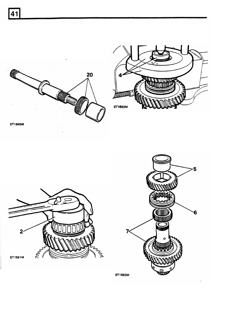
20. Slide drive gear and spacer on
to
the output
4. Secure hand press MS47 in vice with collars
shaft.
18G47BB
-
1
and using button 18G47BB/3
21. Locate output shaft into the bearing in the
remove the rear taper bearing and collars.
housing and drive
into
position.
22.
Locate speedometer gear (driven) housing
assembly into the output housing and press in
until flush with the housing face.
5. Remove the high range gear and bush, taking
care not to disturb the high/low sleeve.
6.
Mark the relationship
of the high/low sleeve to
the hub and then remove the sleeve.
7.
Using a suitable press behind the low range
gear carefully remove the high/low hub and
low
range gear.
Centre differential unit dismantle and overhaul
1. Secure centre differential unit
to a vice
fitted
with
soft jaws, and release stake nut from
recess.
2. Remove stake nut using tool
18G1423
and
suitable socket wrench and discard stake nut.
3.
Remove the differential unit from the vice.
16
REISSUED:
FEB
1993
LT230T TRANSFER GEARBOX
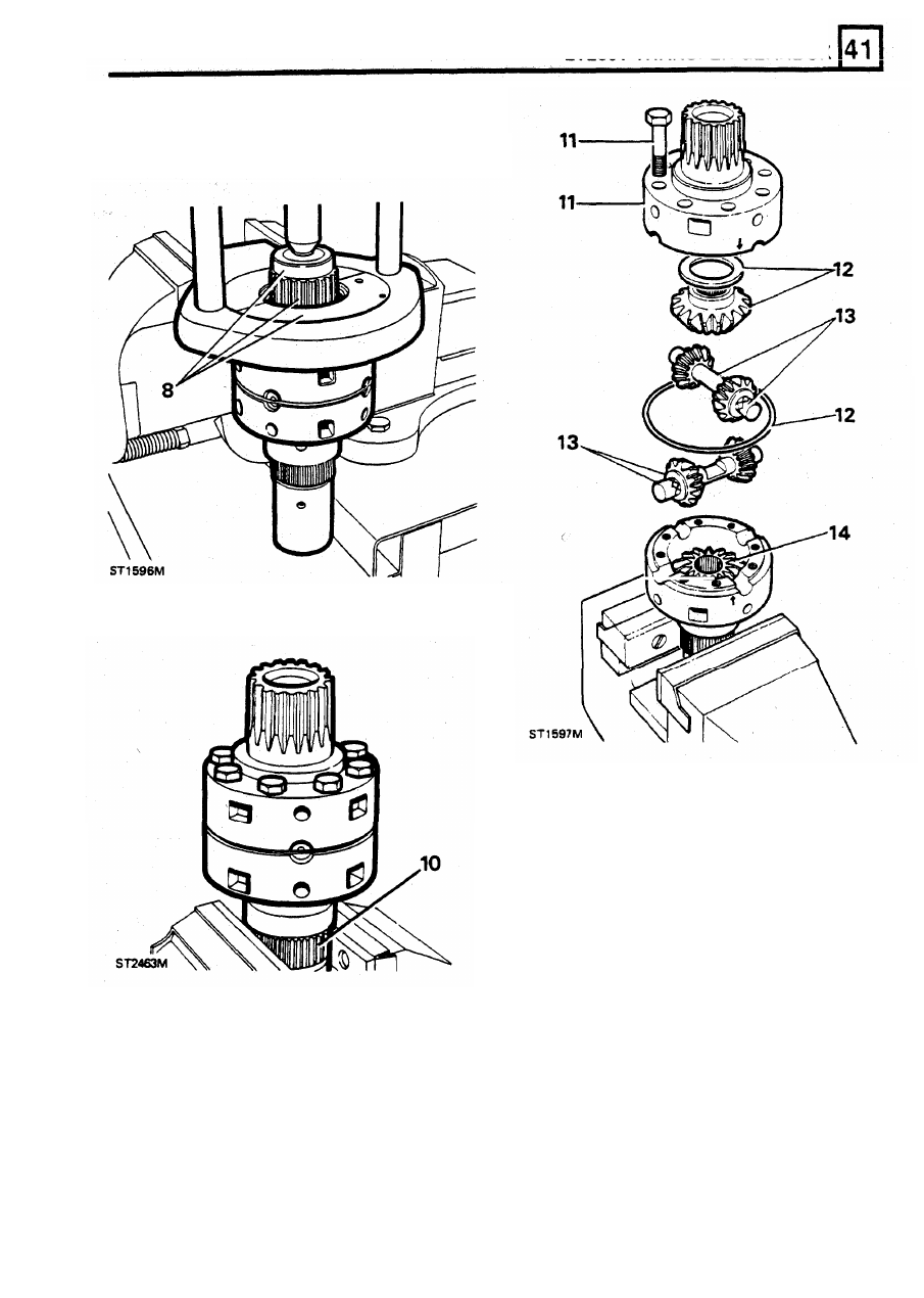
8.
Substituting collar LST47 - 1 remove front
taper roller bearing from the differential.
9.
Remove hand press from the vice.
10.
Using soft jaws secure the differential unit in
the vice by gripping the hub splines.
16.
Inspect all components for damage or wear,
fit
new components
if
necessary.
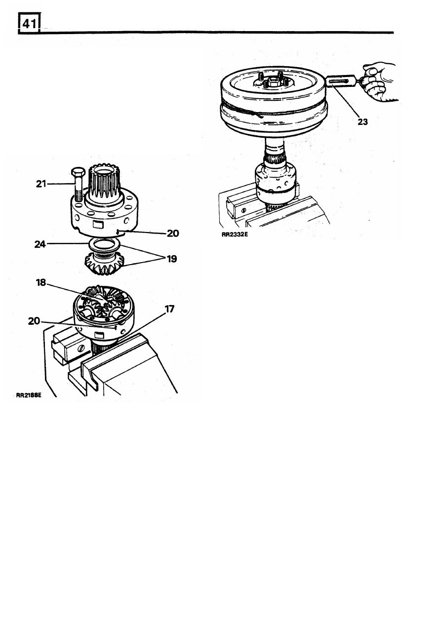
17.
Using
soft jaws secure the rear (longest half)
of the differential unit
in
the vice by gripping
the hub splines.
18.
Lubricate and install the cross shafts and
pinion gears with new dished washers
DO
NOT fit the rear bevel gear at this stage.
11.
Remove the eight retaining bolts and lift off
the front part
of the differential unit.
12.
Release the retaining ring and remove front
upper sun gear and thrust washer.
13.
Remove the planet gears and dished washers
along with the cross shafts.
14.
Remove the rear lower sun gear and thrust
washer from the rear part of the differential
unit.
15.
Remove the rear differential unit from the vice
and clean all components.
REISSUED: FEB 1993
17
LT230T
TRANSFER GEARBOX
19.
Lubricate and
fit
the front bevel gear
and
thinnest thrust washer (FRC6956 1.05mm).
20. Fit the front half of the differential casing
ensuring that the
two engraved arrows are
aligned.
21. Fit securing bolts and tighten
to the correct
torque (see section 06 - TORQUE
VALUES).
22. Lubricate and insert the rear output shaft into
the bevel gear and check that the gears are
free
to
rotate.
NOTE: Gears that have been run
will rotate
smoothly and
will require a torque of
0.56
Nm (5 in lb). Equivalent force using a
spring balance: 0.45 Kg (1 Ib).
New
gears will rotate with a "notchy" feel
and will require a torque of not more than
2.26 Nm (20 in Ib). Equivalent force using a
spring balance: 1.72 Kg (3.8 Ib).
Keep all components well lubricated
when
carrying out these adjustments.
24. Change the thrust washer for a thicker one
if
the torque reading is too low. Five thrust
washers are available
in
0.10
mm steps
ranging from
1.05
to 1,45 mm.
25. Dismantle the unit when the front bevel gear
thrust washer is selected.
26. Remove and retain the front bevel and thrust
23. Fit the transmission brake drum to the output
washer combination.
drive flange and check the torque required
to
27. Reassemble the unit with the rear bevel gear
rotate the gears. Tie a length of string around
and thinnest thrust washer
in
position.
the brake drum, attach a spring balance
to the
28. Using soft jaws secure the front (shortest half)
string and carefully tension the string until a
of the differential unit in the vice by gripping
load to turn
is
obtained, Alternatively use a
the hub splines.
torque wrench applied
to
the brake drum
29. Repeat the above procedure
to obtain the
flange nut. Rotate the drum slowly by hand to
correct thrust washer for the rear bevel gear.
overcome initial load when using either
method. Note that the illustration RR2332E
shows checking torque at rear bevel gear.
18
REISSUED:
FEB
1993
LT230T TRANSFER GEARBOX
Re-assembling centre differential
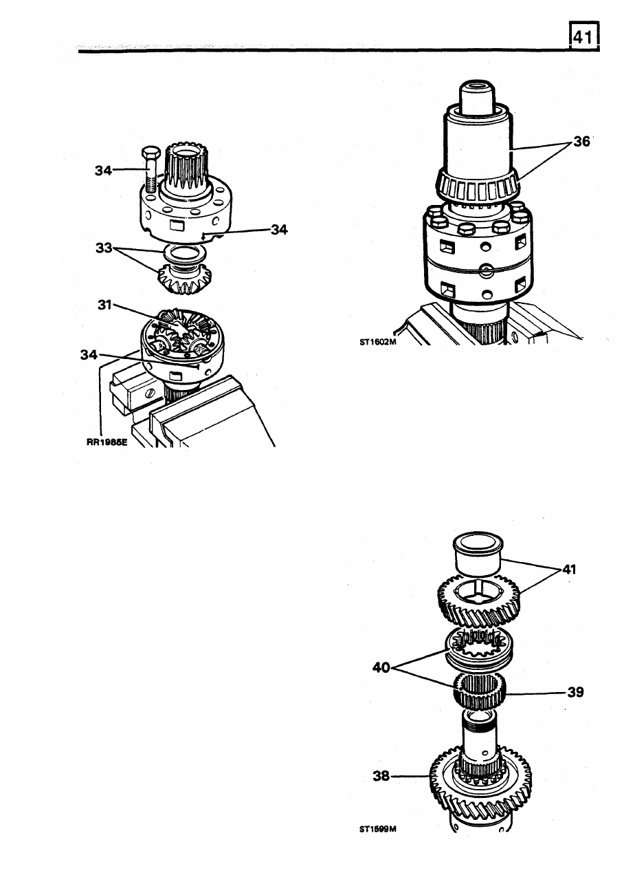
30.
Fit the selected thrust washer and bevel gear
into the rear differential unit.
38. Fit the low range gear, with its dog teeth
uppermost
to
the differential assembly.
39.
Press the high/low hub on
to
the differential
splines.
40. Slide the high/low selector sleeve
on to
the
high/low hub ensuring that the alignment
marks are opposite each other.
41. Fit the bush into
the
high range gear
so that
the flange is fitted on the opposite side of the
gear
to the dog teeth. Slide the bushed gear
on to the differential assembly with the dog
teeth down.
31.
Assemble both pinion assemblies and dished
washers onto their respective shafts and fit
the
rear
differential
unit.
Secure
the
assemblies with the retaining ring.
32. Lubricate all the components.
33. Fit the selected thrust washer and bevel gear
into the front upper differential unit.
34. Align both units as previously described and
secure with the eight bolts
to the specified
torque.
35. Check the overall torque required to turn the
differential. This should be approximately
equal to the resistance
of both bevel gears
added together.
36. Locate the front differential bearing onto the
front, upper differential shaft and press into
position using larger end of
tool 18G1424 as
shown.
37.
Invert the differential unit and secure in the
vice.
NOTE: During the following sequences all
parts should be lubricated as they are
fitted.
RElSSUED:
FEB
1993
19
Нет комментариевНе стесняйтесь поделиться с нами вашим ценным мнением.
Текст